TP-114 specifications
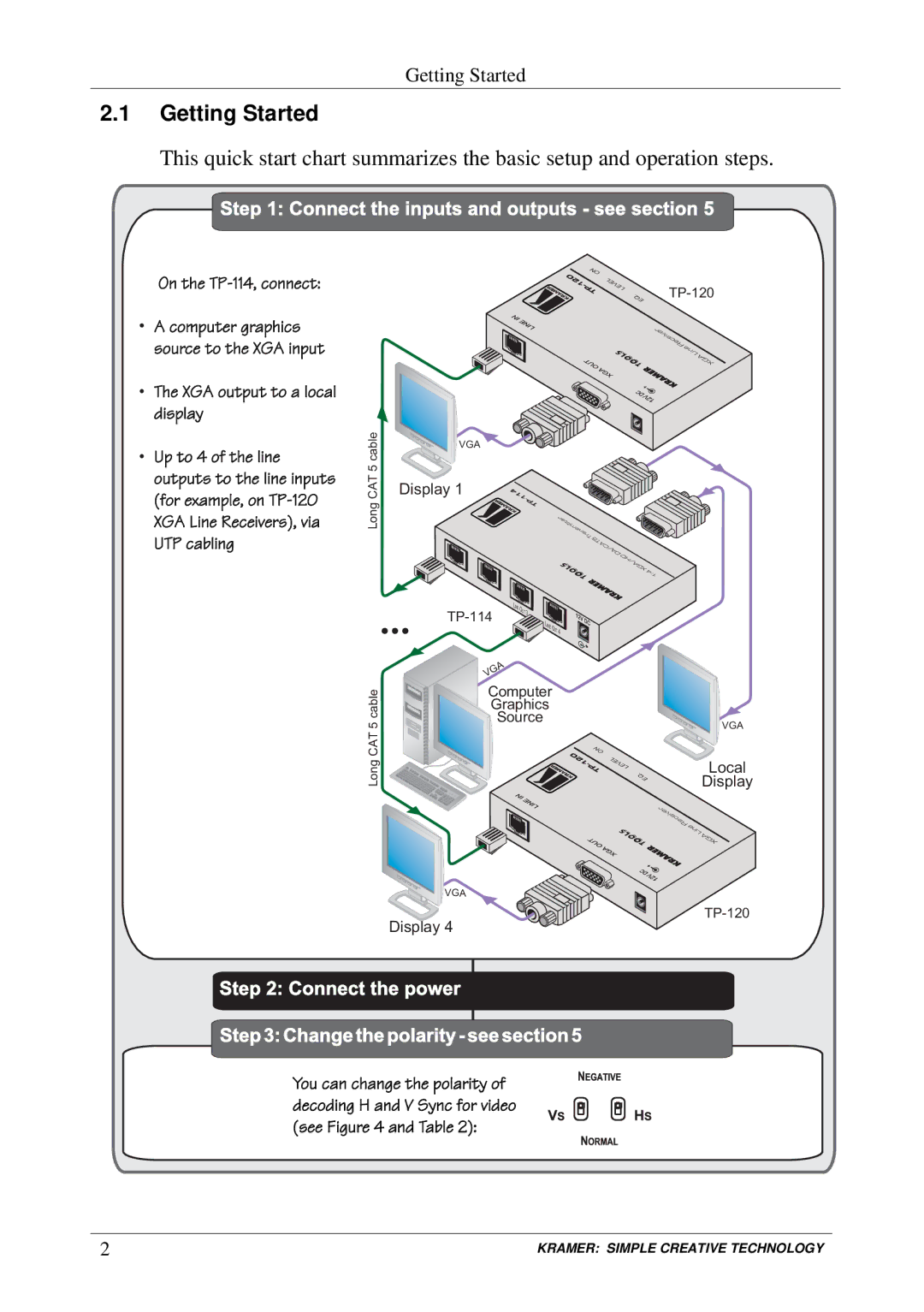
Kramer Electronics TP-114 is a high-quality transmission device designed for professionals in the audiovisual and broadcasting industries. This device offers reliable signal management and ensures that audio and video signals maintain their integrity over long distances. The TP-114 is especially well-suited for applications requiring the extension of signals via twisted pair cabling, making it an ideal choice for both live events and permanent installations.One of the standout features of the TP-114 is its ability to transmit HDMI signals up to a distance of 70 meters (230 feet) at 4K resolution. This capability is essential for environments where high-definition content is critical, such as in control rooms, conference halls, and large venues. The device employs advanced signal processing technologies to minimize latency and ensure synchronization between audio and video output.
The TP-114 supports a variety of audio and video formats, including Deep Color, 3D, and high-definition multi-channel audio. This versatility allows users to work flexibly with a wide range of media types and ensures compatibility with various devices, from laptops to advanced broadcasting equipment. Additionally, the TP-114 also provides EDID (Extended Display Identification Data) management, allowing for seamless communication with connected displays and facilitations in managing video resolutions.
Constructed with a user-friendly design, the TP-114 features intuitive LED indicators that provide real-time feedback on the operational status, including power supply and signal transmission status. This is a valuable characteristic that aids technicians in troubleshooting issues promptly while performing live or recorded productions. The device's robust build quality ensures durability and longevity, making it a sound investment for any professional setup.
Moreover, the TP-114’s lightweight design and compact form factor enable effortless integration into existing systems. It can be mounted in various rack environments or used as a standalone unit. The inclusion of multiple I/O ports enhances flexibility in connecting various sources and displays, streamlining the workflow in any audiovisual project.
Overall, Kramer Electronics TP-114 stands out as an exemplary solution for those seeking reliable and efficient HDMI signal extension. With its combination of high-performance capabilities, user-centered design, and technological advancements, the TP-114 continues to be a go-to choice for professionals in the ever-evolving audiovisual landscape.

