3 LED Indicators
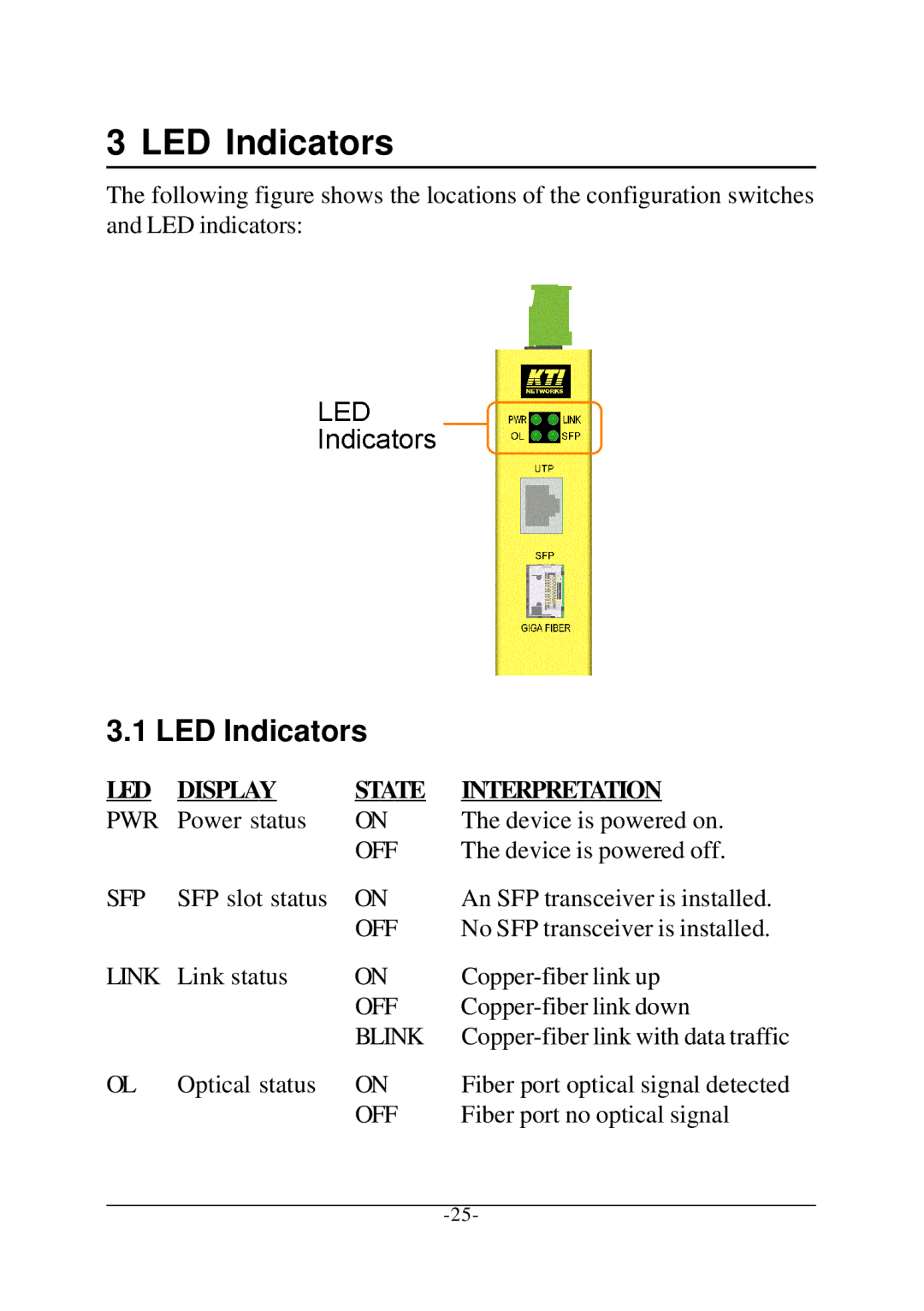
The following figure shows the locations of the configuration switches and LED indicators:
3.1 LED Indicators
LED | DISPLAY | STATE | INTERPRETATION |
PWR | Power status | ON | The device is powered on. |
|
| OFF | The device is powered off. |
SFP | SFP slot status | ON | An SFP transceiver is installed. |
|
| OFF | No SFP transceiver is installed. |
LINK | Link status | ON | |
|
| OFF | |
|
| BLINK | |
OL | Optical status | ON | Fiber port optical signal detected |
|
| OFF | Fiber port no optical signal |