Manuals
/
Kunz
/
Lawn and Garden
/
Lawn Mower
Kunz
MR44B, MR44K
owner manual
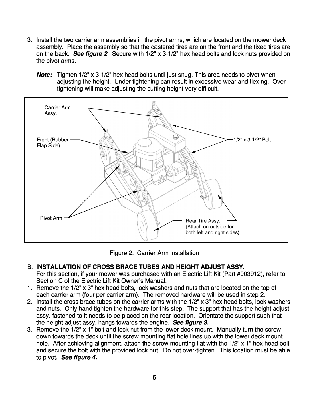
B. Installation Of Cross Brace Tubes And Height Adjust Assy
Models:
MR44K
MR44B
1
6
23
23
Download
23 pages
50.91 Kb
3
4
5
6
7
8
9
10
Dimension
With Assembly Instructions
Operations And Adjustments
Safety
Page 6
Image 6
Page 5
Page 7
Page 6
Image 6
Page 5
Page 7
Contents
KUNZ ENGINEERING, INC. / MENDOTA, IL 61342 / PH
With Assembly Instructions
For Models MR44B & MR44K
1/09
SAFETY INTRODUCTION
IMPORTANT SAFETY INFORMATION
275003 - Danger
SAFETY SIGNS AND LOCATIONS
Clean or Replace Any Safety Signs That Are not Readable or Damaged
275007 - Warning
You should have
ASSEMBLY INSTRUCTIONS
A. ASSEMBLY OF REAR WHEELS AND CARRIER ARMS
Read the complete assembly instructions before starting the assembly
B. INSTALLATION OF CROSS BRACE TUBES AND HEIGHT ADJUST ASSY
Figure 3 Cross Brace Tube Installation
C. INSTALLATION OF TONGUE ASSEMBLY
Offset Position
Direct Behind Position
OPERATIONS AND ADJUSTMENTS
A. TONGUE CONFIGURATIONS AND ADJUSTMENTS
B. ADJUSTING CUTTING HEIGHT
Adjust the mower as follows
C. STARTING ENGINE
D. SHUTTING OFF ROUGH CUT MOWER
E. MOWER OPERATION
WARNING Do not fill fuel tank while engine is running or hot
F. DRIVE BELT REMOVAL AND TENSION - Refer to Figure
Disengaged Spring Length
Brake Stud Clearance
G. MOWER BLADE REMOVAL, BALANCING & INSTALLATION
H. LUBRICATION
I. STORAGE
Model
ACREASE ROUGH CUT MOWER SPECIFICATIONS
DIMENSIONS
ENGINE
ACREASE ROUGH CUT MOWER PARTS LIST
Description
Description
UACREASE 44” ROUGH CUT MOWER PARTS
2933
OPTIONAL EQUIPMENT
OPTIONAL WETLANDS KIT
Shown on the 57” Rough Cut Mower
OPTIONAL ELECTRIC LIFT KIT
OPTIONALUEQUIPMENT
OPTIONAL FLOATATION KIT
Top
Page
Image
Contents