FEATURES
The Temperature Station
∙Manual time set (hour and minute)
∙12-Hour Time Format
∙Temperature Display in Farenheit (°F)
∙Indoor and Outdoor Temperature with MIN/MAX Records
∙Low Battery Indicator
∙Wireless Transmission at 915 MHz
∙8 Second Signal Reception Interval
∙Wall Mount or Table Stand
The Outdoor Temperature Transmitter
∙ Wireless 915 MHz Outdoor Temperature Transmitter
∙ Rain-resistant Casing
∙ Wall Mounting or Table Stand
Note: Mount in a sheltered place. Avoid direct rain and sunshine.
SETUP
IMPORTANT: Do not mix old and new batteries. Do not mix alkaline, standard (carbon-zinc), or rechargeable (nickel cadmium) batteries.
Note: This temperature station can only receive one transmitter only.
1.First, insert batteries into the transmitter, observing the correct polarity (see marking inside battery compartment).
2.Within 30 seconds of powering up the transmitter, insert batteries into the Temperature Station, observing the correct polarity (see marking inside battery compartment). Once the batteries are in place, all segments of the LCD will light up briefly. Following the indoor temperature, the time as 12:00 will be displayed. If they are not shown in the LCD after 60 seconds, remove the batteries and wait for at least 60 seconds before reinserting them. Once the indoor data is displayed you may proceed to the next step.
3.After the batteries are inserted, the Temperature Station will start receiving outdoor temp data from the transmitter. The outdoor temperature should then be displayed on the Temperature station. If this does not happen after 2 minutes, remove the batteries from both units and start again from step 1.
4.In order to ensure sufficient 915 MHz transmission, the outdoor transmitter should be placed a distance of no more than 200 feet (60 meters) from the Temperature Station and the transmitter (see notes on “Positioning”).
FUNCTION KEYS
The Temperature Station has only two easy to use function keys:
SET key 


 + key
+ key
SET key: | Press and hold for about 3 seconds to enter the Manual setting mode. |
+ key: | Press to make adjustment in the setting mode. Press and hold to reset all MIN/MAX |
| records |
4. | The minute digit will be flashing. Press the + key to adjust the minute (press and hold to |
| allow fast advance). Press SET key once more to return to normal display. |
Note: If no buttons are pressed within approximately 8 seconds while in setting mode, the unit will return to normal operating mode.
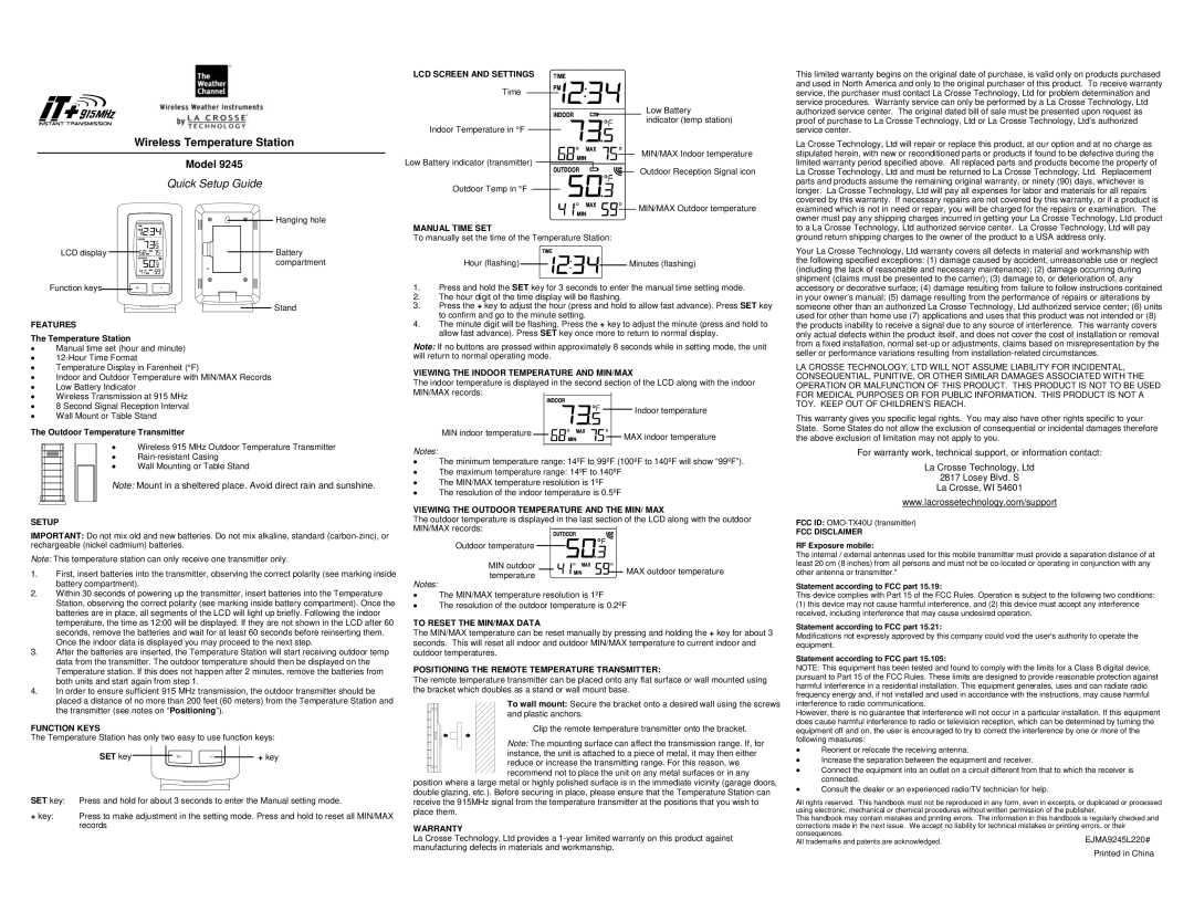
VIEWING THE INDOOR TEMPERATURE AND MIN/MAX
The indoor temperature is displayed in the second section of the LCD along with the indoor MIN/MAX records:
MIN indoor temperature | | | | | | Indoor temperature |
| | | | |
| | | | MAX indoor temperature |
| | |
| | | | |
Notes:
∙The minimum temperature range: 14ºF to 99ºF (100ºF to 140ºF will show “99ºF”).
∙The maximum temperature range: 14ºF to 140ºF
∙The MIN/MAX temperature resolution is 1ºF
∙The resolution of the indoor temperature is 0.5ºF
VIEWING THE OUTDOOR TEMPERATURE AND THE MIN/ MAX
The outdoor temperature is displayed in the last section of the LCD along with the outdoor MIN/MAX records:
Outdoor temperature
| MIN outdoor | MAX outdoor temperature |
| temperature |
| |
Notes:
∙The MIN/MAX temperature resolution is 1ºF
∙The resolution of the outdoor temperature is 0.2ºF
TO RESET THE MIN/MAX DATA
The MIN/MAX temperature can be reset manually by pressing and holding the + key for about 3 seconds. This will reset all indoor and outdoor MIN/MAX temperature to current indoor and outdoor temperatures.
POSITIONING THE REMOTE TEMPERATURE TRANSMITTER:
The remote temperature transmitter can be placed onto any flat surface or wall mounted using the bracket which doubles as a stand or wall mount base.
To wall mount: Secure the bracket onto a desired wall using the screws and plastic anchors.
Clip the remote temperature transmitter onto the bracket.
Note: The mounting surface can affect the transmission range. If, for
instance, the unit is attached to a piece of metal, it may then either
reduce or increase the transmitting range. For this reason, we recommend not to place the unit on any metal surfaces or in any
position where a large metal or highly polished surface is in the immediate vicinity (garage doors, double glazing, etc.). Before securing in place, please ensure that the Temperature Station can receive the 915MHz signal from the temperature transmitter at the positions that you wish to place them.
WARRANTY
La Crosse Technology, Ltd provides a 1-year limited warranty on this product against manufacturing defects in materials and workmanship.
the products inability to receive a signal due to any source of interference. This warranty covers only actual defects within the product itself, and does not cover the cost of installation or removal from a fixed installation, normal set-up or adjustments, claims based on misrepresentation by the seller or performance variations resulting from installation-related circumstances.
LA CROSSE TECHNOLOGY, LTD WILL NOT ASSUME LIABILITY FOR INCIDENTAL, CONSEQUENTIAL, PUNITIVE, OR OTHER SIMILAR DAMAGES ASSOCIATED WITH THE OPERATION OR MALFUNCTION OF THIS PRODUCT. THIS PRODUCT IS NOT TO BE USED FOR MEDICAL PURPOSES OR FOR PUBLIC INFORMATION. THIS PRODUCT IS NOT A TOY. KEEP OUT OF CHILDREN’S REACH.
This warranty gives you specific legal rights. You may also have other rights specific to your State. Some States do not allow the exclusion of consequential or incidental damages therefore the above exclusion of limitation may not apply to you.
For warranty work, technical support, or information contact:
La Crosse Technology, Ltd
2817 Losey Blvd. S
La Crosse, WI 54601
www.lacrossetechnology.com/support
FCC ID: OMO-TX40U (transmitter)
FCC DISCLAIMER
RF Exposure mobile:
The internal / external antennas used for this mobile transmitter must provide a separation distance of at least 20 cm (8 inches) from all persons and must not be co-located or operating in conjunction with any other antenna or transmitter."
Statement according to FCC part 15.19:
This device complies with Part 15 of the FCC Rules. Operation is subject to the following two conditions:
(1)this device may not cause harmful interference, and (2) this device must accept any interference received, including interference that may cause undesired operation.
Statement according to FCC part 15.21:
Modifications not expressly approved by this company could void the user's authority to operate the equipment.
Statement according to FCC part 15.105:
NOTE: This equipment has been tested and found to comply with the limits for a Class B digital device, pursuant to Part 15 of the FCC Rules. These limits are designed to provide reasonable protection against harmful interference in a residential installation. This equipment generates, uses and can radiate radio frequency energy and, if not installed and used in accordance with the instructions, may cause harmful interference to radio communications.
However, there is no guarantee that interference will not occur in a particular installation. If this equipment does cause harmful interference to radio or television reception, which can be determined by turning the equipment off and on, the user is encouraged to try to correct the interference by one or more of the following measures:
∙Reorient or relocate the receiving antenna.
∙Increase the separation between the equipment and receiver.
∙Connect the equipment into an outlet on a circuit different from that to which the receiver is connected.
∙Consult the dealer or an experienced radio/TV technician for help.
All rights reserved. This handbook must not be reproduced in any form, even in excerpts, or duplicated or processed using electronic, mechanical or chemical procedures without written permission of the publisher.
This handbook may contain mistakes and printing errors. The information in this handbook is regularly checked and corrections made in the next issue. We accept no liability for technical mistakes or printing errors, or their consequences.
All trademarks and patents are acknowledged. | EJMA9245L220# |
| Printed in China |