POSITIONING
Before permanently mounting ensure that the atomic clock is able to receive WWVB signals from the desired location. Also, extreme and sudden changes in temperature will decrease the accuracy of the atomic clock, and changes in elevation will result with inaccurate temperatures readings for the next 12 to 24 hours. These changes will require a 12 to 24 hour wait before obtaining reliable data.
To achieve a true temperature reading, avoid mounting where direct sunlight can reach the outdoor temperature sensor. It is recommended to mount the outdoor temperature sensor on a
Place both units in their desired location, and wait approximately 10 minutes before permanently mounting to ensure that there is proper reception. The outdoor temperature sensor is not waterproof and should not be placed anywhere it will become submerged in water or be directly in the rain.
POSITIONING THE ATOMIC CLOCK:
There are two possible ways to mount the atomic clock:
•use of the foldout table stands, or
•wall mounting
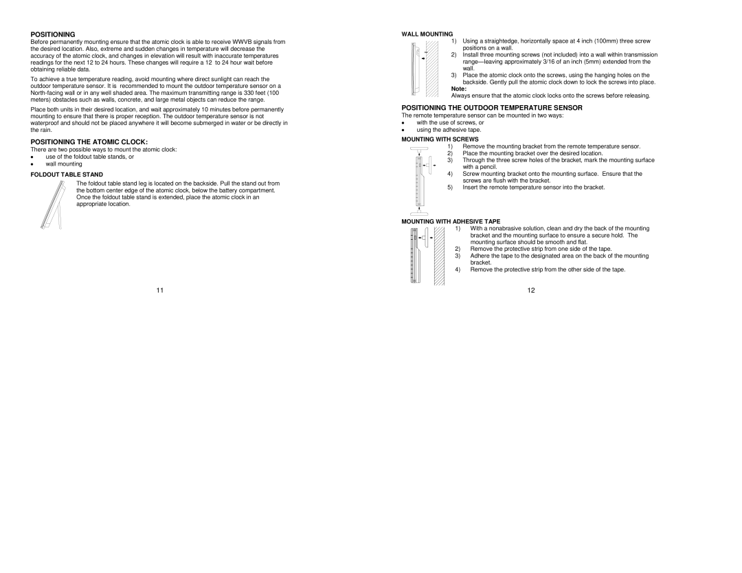
FOLDOUT TABLE STAND
The foldout table stand leg is located on the backside. Pull the stand out from the bottom center edge of the atomic clock, below the battery compartment. Once the foldout table stand is extended, place the atomic clock in an appropriate location.
11
WALL MOUNTING
1) Using a straightedge, horizontally space at 4 inch (100mm) three screw positions on a wall.
2) Install three mounting screws (not included) into a wall within transmission
3)Place the atomic clock onto the screws, using the hanging holes on the
backside. Gently pull the atomic clock down to lock the screws into place.
Note:
Always ensure that the atomic clock locks onto the screws before releasing.
POSITIONING THE OUTDOOR TEMPERATURE SENSOR
The remote temperature sensor can be mounted in two ways:
•with the use of screws, or
•using the adhesive tape.
MOUNTING WITH SCREWS
1)Remove the mounting bracket from the remote temperature sensor.
|
| 2) | Place the mounting bracket over the desired location. | ||||||||||
|
|
|
|
|
|
|
| 3) | Through the three screw holes of the bracket, mark the mounting surface | ||||
|
|
|
|
|
|
|
|
|
|
|
|
| with a pencil. |
|
|
|
|
|
|
|
|
|
|
|
|
| |
|
|
|
| 4) | Screw mounting bracket onto the mounting surface. Ensure that the | ||||||||
|
|
|
|
|
| ||||||||
|
|
|
|
|
|
|
|
|
|
|
|
| screws are flush with the bracket. |
|
|
|
| 5) | Insert the remote temperature sensor into the bracket. | ||||||||
|
|
| |||||||||||
|
|
|
|
|
| ||||||||
|
|
|
|
|
| ||||||||
|
|
|
|
|
| ||||||||
|
|
| |||||||||||
MOUNTING WITH ADHESIVE TAPE | |||||||||||||
|
|
|
|
|
|
|
|
|
|
|
| 1) | With a nonabrasive solution, clean and dry the back of the mounting |
|
|
|
|
|
|
|
|
| |||||
|
|
|
|
|
|
|
|
|
|
|
|
| bracket and the mounting surface to ensure a secure hold. The |
|
|
|
|
|
|
|
|
|
|
|
|
| mounting surface should be smooth and flat. |
|
|
|
|
|
|
|
|
|
|
|
| 2) | Remove the protective strip from one side of the tape. |
|
|
|
|
|
|
|
|
|
|
| 3) | Adhere the tape to the designated area on the back of the mounting | |
| |||||||||||||
| |||||||||||||
|
|
|
|
|
|
|
|
|
|
|
|
| bracket. |
|
|
|
|
|
|
|
|
|
|
|
|
| |
|
|
|
|
|
|
|
|
|
|
| 4) | Remove the protective strip from the other side of the tape. | |
| |||||||||||||
|
|
|
|
|
|
|
|
|
|
|
|
|
|
|
|
|
|
|
|
|
|
|
|
|
|
|
|
|
|
|
|
|
|
|
|
|
|
|
|
|
|
12