Page 14

WATERPIK TECHNOLOGIES INC.


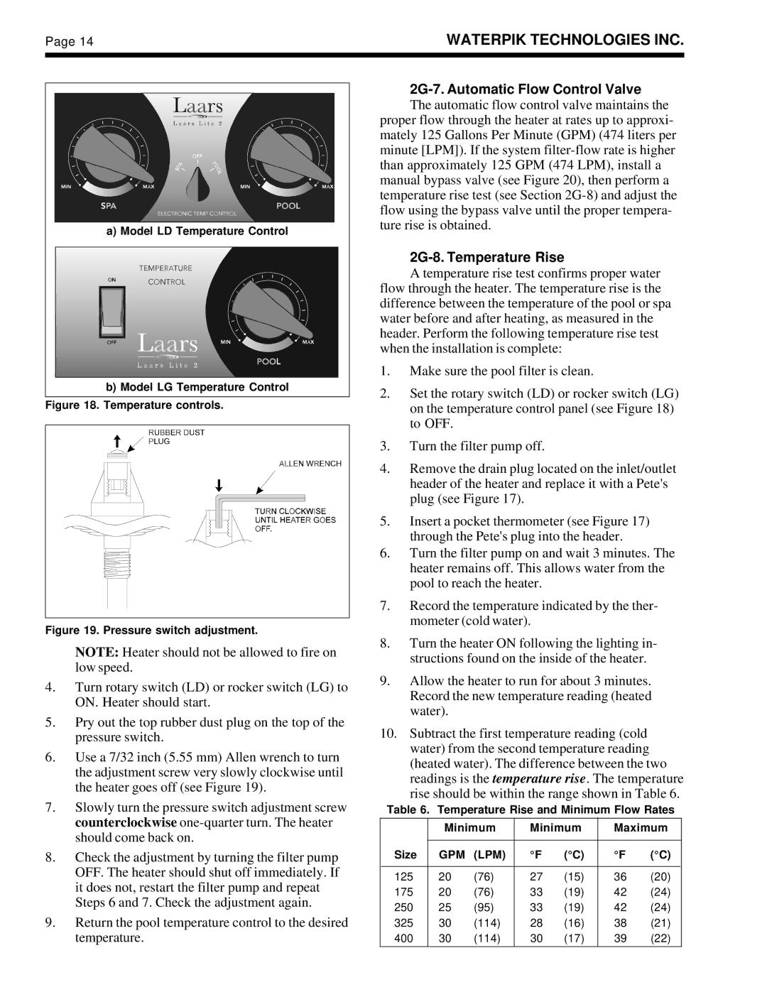
a) Model LD Temperature Control

b)Model LG Temperature Control

Figure 18. Temperature controls.

Figure 19. Pressure switch adjustment.

NOTE: Heater should not be allowed to fire on low speed.

4.Turn rotary switch (LD) or rocker switch (LG) to ON. Heater should start.

5.Pry out the top rubber dust plug on the top of the pressure switch.

6.Use a 7/32 inch (5.55 mm) Allen wrench to turn the adjustment screw very slowly clockwise until the heater goes off (see Figure 19).

7.Slowly turn the pressure switch adjustment screw counterclockwise one-quarter turn. The heater should come back on.

8.Check the adjustment by turning the filter pump OFF. The heater should shut off immediately. If it does not, restart the filter pump and repeat Steps 6 and 7. Check the adjustment again.

9.Return the pool temperature control to the desired temperature.

2G-7. Automatic Flow Control Valve

The automatic flow control valve maintains the proper flow through the heater at rates up to approxi- mately 125 Gallons Per Minute (GPM) (474 liters per minute [LPM]). If the system filter-flow rate is higher than approximately 125 GPM (474 LPM), install a manual bypass valve (see Figure 20), then perform a temperature rise test (see Section 2G-8) and adjust the flow using the bypass valve until the proper tempera- ture rise is obtained.

2G-8. Temperature Rise

A temperature rise test confirms proper water flow through the heater. The temperature rise is the difference between the temperature of the pool or spa water before and after heating, as measured in the header. Perform the following temperature rise test when the installation is complete:

1.Make sure the pool filter is clean.

2.Set the rotary switch (LD) or rocker switch (LG) on the temperature control panel (see Figure 18) to OFF.

3.Turn the filter pump off.

4.Remove the drain plug located on the inlet/outlet header of the heater and replace it with a Pete's plug (see Figure 17).

5.Insert a pocket thermometer (see Figure 17) through the Pete's plug into the header.

6.Turn the filter pump on and wait 3 minutes. The heater remains off. This allows water from the pool to reach the heater.

7.Record the temperature indicated by the ther- mometer (cold water).

8.Turn the heater ON following the lighting in- structions found on the inside of the heater.

9.Allow the heater to run for about 3 minutes. Record the new temperature reading (heated water).

10.Subtract the first temperature reading (cold water) from the second temperature reading (heated water). The difference between the two readings is the temperature rise. The temperature rise should be within the range shown in Table 6.

Table 6. Temperature Rise and Minimum Flow Rates


Minimum

Minimum

Maximum


Size

GPM

(LPM)

°F

(°C)

°F

(°C)


125

20

(76)

27

(15)

36

(20)

175

20

(76)

33

(19)

42

(24)

250

25

(95)

33

(19)

42

(24)

325

30

(114)

28

(16)

38

(21)

400

30

(114)

30

(17)

39

(22)


Page 16
Image 16
Laarsen Associates LG, LD operation manual 2G-7. Automatic Flow Control Valve, 2G-8. Temperature Rise

LG, LD specifications

Laarsen Associates is a reputable engineering and consulting firm known for its innovative solutions in the field of energy and environmental management. Among its notable offerings are the LG and LD series of products, designed to optimize energy efficiency and reduce environmental impact in various applications.

The LG series focuses on providing high-performance tools for efficient energy management in commercial settings. These tools are engineered to integrate seamlessly into existing infrastructures, allowing businesses to monitor, control, and optimize their energy consumption effectively. One of the main features of the LG series is its user-friendly interface, which provides real-time data on energy usage, enabling users to make informed decisions quickly. Furthermore, the enhanced connectivity options facilitate remote access, allowing users to manage their systems from anywhere, significantly improving flexibility and response times.

On the other hand, the LD series is tailored for industrial applications, emphasizing durability and robust performance. The LD products are designed to withstand the harshest environments while maintaining consistent efficiency. Their advanced monitoring systems provide detailed insights into energy consumption patterns, allowing for predictive maintenance and reduced operational costs. Key characteristics of the LD series include high reliability, modular design, and adaptive technologies that can be customized to suit specific industrial requirements.

Both series employ cutting-edge technologies to achieve optimal performance. Smart sensors collect real-time data, which is processed using advanced algorithms to deliver actionable insights. These insights can lead to optimized processes, reduced energy wastage, and enhanced sustainability measures. Moreover, the integration of IoT capabilities allows for smarter energy systems that adapt in real time to changing conditions.

Sustainability is at the core of Laarsen Associates’ offerings. Both the LG and LD series are designed with a commitment to reducing carbon footprints and complying with global standards for environmental protection. Their features not only promote energy efficiency but also support clients in achieving their sustainability goals.

In conclusion, Laarsen Associates’ LG and LD series represent the forefront of energy management and environmental solutions. With their combination of user-centric design, advanced technology, and commitment to sustainability, these products pave the way for businesses and industries to navigate modern energy challenges effectively.