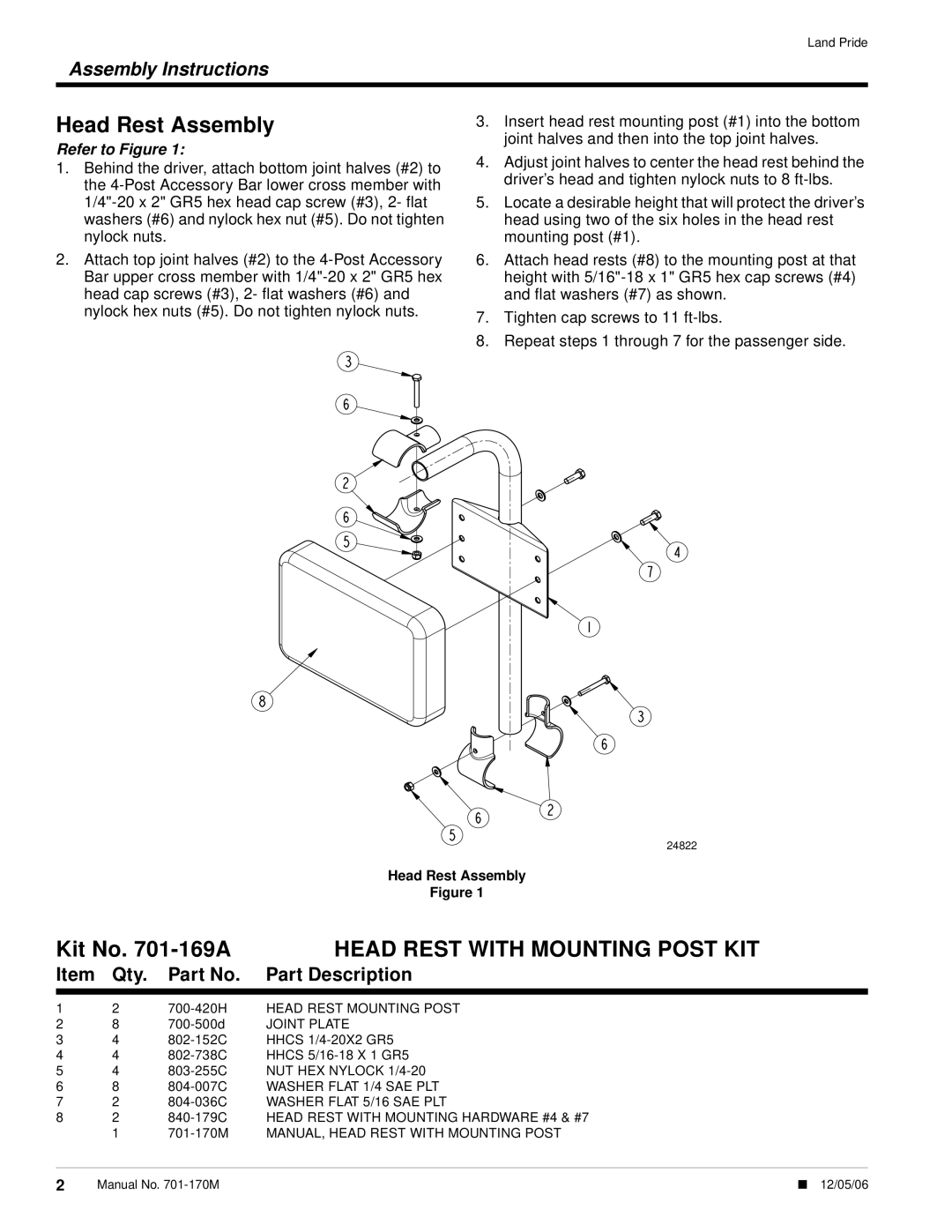
4220ST specifications
The Land Pride 4420ST and 4220ST are top-of-the-line compact tractors designed to meet the diverse needs of farmers, landscapers, and homeowners. These models excel in performance, versatility, and ease of use, making them ideal for a wide range of applications, from landscaping to small-scale farming.One of the standout features of the Land Pride 4420ST and 4220ST is their robust engine options. They come equipped with high-performance diesel engines that provide excellent torque and power, ensuring that users can tackle tough tasks with ease. The efficient fuel consumption contributes to lower operating costs, making them economically sound investments for any operation.
Both models offer a user-friendly hydrostatic transmission, which allows for smooth operation and precise control over speed and direction. This technology enables operators to effortlessly shift from forward to reverse without using a clutch, making it particularly beneficial for tasks that require frequent changes in direction, such as loading, towing, and maneuvering in tight spaces.
Another notable characteristic of the Land Pride 4420ST and 4220ST is their superior hydraulic system. With high flow rates and enhanced control, these models can power a wide range of attachments, from loaders and backhoes to tillers and mowers. The quick-attach feature for implements makes switching between tasks a hassle-free process, increasing productivity on the job.
The design of the 4420ST and 4220ST emphasizes comfort and ease of operation. The spacious operator platform, adjustable seat, and ergonomic controls ensure that users can work for extended periods without discomfort. Additionally, the intuitive dashboard provides vital information at a glance, allowing operators to monitor performance effortlessly.
Safety is a top priority in the design of these tractors. They come equipped with ROPS (Roll-Over Protective Structure) to safeguard operators in the event of a rollover, as well as advanced braking systems that provide quick stopping power under various conditions.
In summary, the Land Pride 4420ST and 4220ST combine power, efficiency, and user-friendly features in compact tractors that are perfect for any agricultural task or property maintenance. Their innovative technology and thoughtful design elements make them valuable assets for anyone seeking reliability and performance in their equipment.

