Table of Contents
Section 1 Assembly and Setup
Land Pride
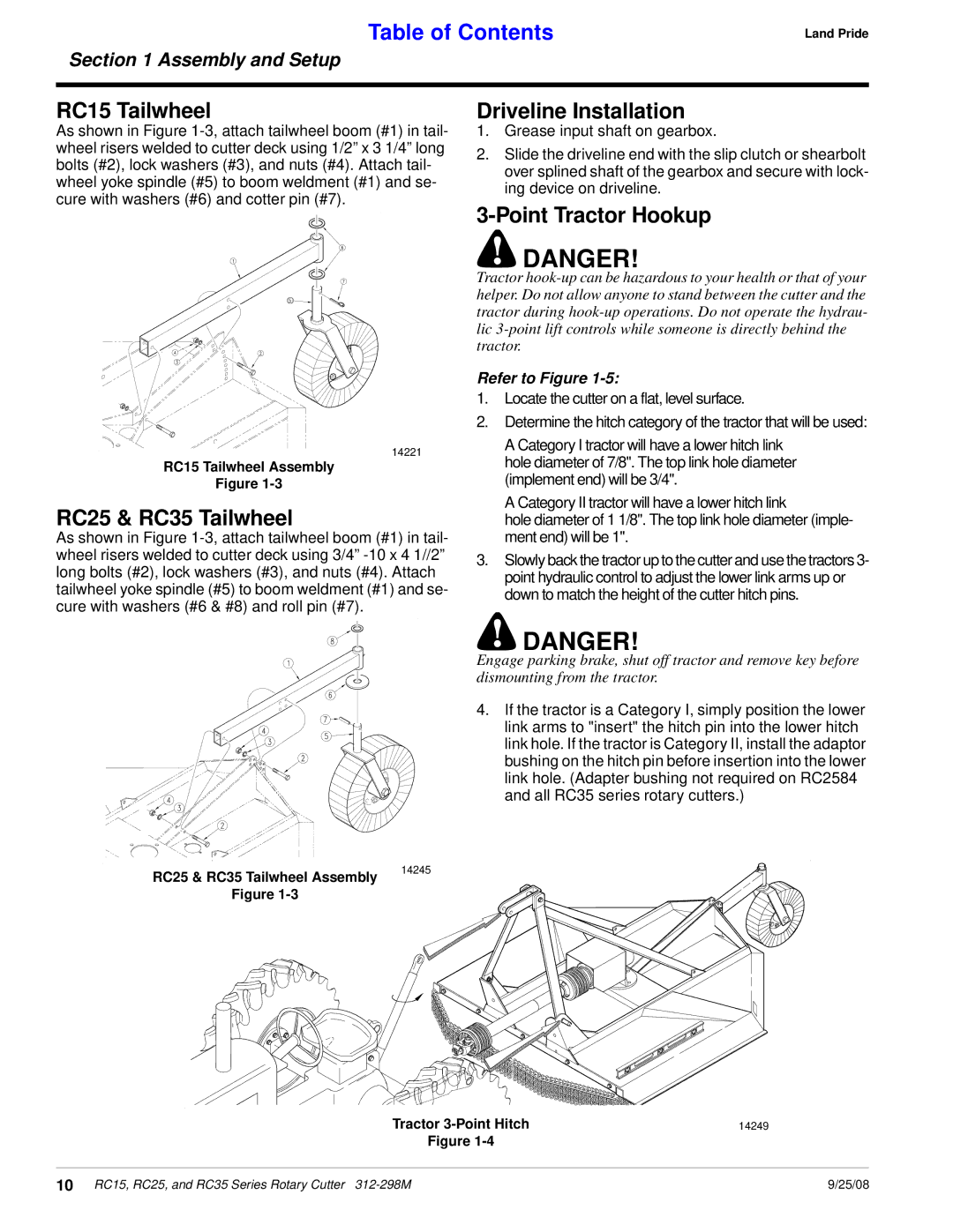
RC15 Tailwheel
As shown in Figure
14221
RC15 Tailwheel Assembly
Figure
RC25 & RC35 Tailwheel
As shown in Figure
Driveline Installation
1.Grease input shaft on gearbox.
2.Slide the driveline end with the slip clutch or shearbolt over splined shaft of the gearbox and secure with lock- ing device on driveline.
3-Point Tractor Hookup
!DANGER!
Tractor
Refer to Figure 1-5:
1.Locate the cutter on a flat, level surface.
2.Determine the hitch category of the tractor that will be used:
A Category I tractor will have a lower hitch link hole diameter of 7/8". The top link hole diameter (implement end) will be 3/4".
A Category II tractor will have a lower hitch link
hole diameter of 1 1/8". The top link hole diameter (imple- ment end) will be 1".
3.Slowly back the tractor up to the cutter and use the tractors 3- point hydraulic control to adjust the lower link arms up or down to match the height of the cutter hitch pins.
RC25 & RC35 Tailwheel Assembly
Figure
! DANGER!
Engage parking brake, shut off tractor and remove key before dismounting from the tractor.
4. If the tractor is a Category I, simply position the lower link arms to "insert" the hitch pin into the lower hitch link hole. If the tractor is Category II, install the adaptor bushing on the hitch pin before insertion into the lower link hole. (Adapter bushing not required on RC2584 and all RC35 series rotary cutters.)
14245
Tractor | 14249 |
Figure |
|
10 RC15, RC25, and RC35 Series Rotary Cutter | 9/25/08 |
