INSTALLING OFFSETS

First, review the Offset Elevation Chart and Figure 38 for reference.

Step 1. Determine the offset distance where chimney is to pass through the first ceiling- dimension “A.” To find this point on your ceil- ing, first determine the center point for a verti- cal chimney following the instructions for ver- tical installation.

Measure height to the ceiling from the top of fireplace-dimension “B.” Use the appropriate Offset Elevation Chart to find dimension “A.” Mark point where you will drive your nail to show the center point for your offset ceiling cut.

Step 2. Proceed by using the Straight Up Instal- lation Instructions for cutting and framing ceil- ing and roof openings.

Note: See Framing and Dimension Chart for the sizes of the ceiling and roof openings. The size of the roof opening varies with the degree of pitch of the roof.

Offset Elbow Assembly

Offset elbows install the same as chimney sections. First, snap the inner section INTO the preceding inner section of flue. Check connec- tion by pulling up slightly to ensure a tight fit. Next, the outer sections snap lock OVER the preceding outer section of chimney. Again, check outer section by pulling up slightly to ensure proper connection is made.

Return Elbow Assembly

Return elbows install the same way as round terminations and stabilizers:

Step 1. Hold return elbow over top of last chimney section.

Step 2. Center inner slip section into inner flue pipe-slip down.

Step 3. Center outer-locking section over outer chimney pipe. Push down until locking joint has firmly engaged.

Step 4. Pull up slightly on return elbow to ensure locking joint has firmly engaged.

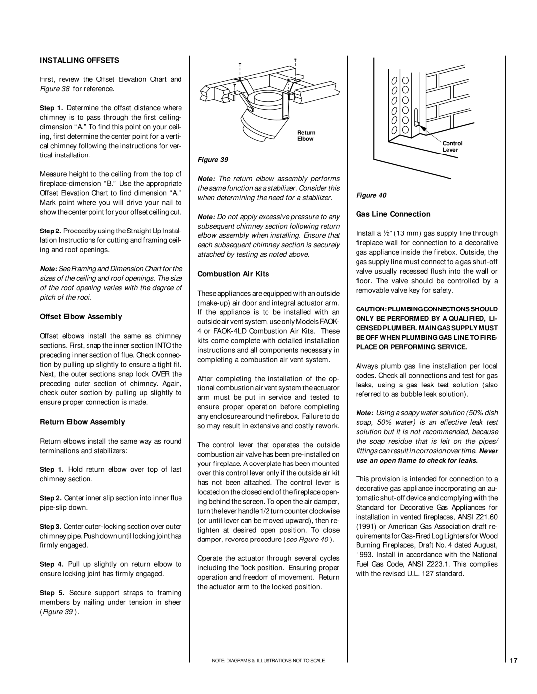
Step 5. Secure support straps to framing members by nailing under tension in sheer (Figure 39 ).

Return

Elbow

Figure 39

Note: The return elbow assembly performs the same function as a stabilizer. Consider this when determining the need for a stabilizer.

Note: Do not apply excessive pressure to any subsequent chimney section following return elbow assembly when installing. Ensure that each subsequent chimney section is securely attached by testing as noted above.

Combustion Air Kits

These appliances are equipped with an outside (make-up) air door and integral actuator arm. If the appliance is to be installed with an outside air vent system, use only Models FAOK- 4 or FAOK-4LD Combustion Air Kits. These kits come complete with detailed installation instructions and all components necessary in completing a combustion air vent system.

After completing the installation of the op- tional combustion air vent system the actuator arm must be put in service and tested to ensure proper operation before completing any enclosure around the firebox. Failure to do so may result in extensive and costly rework.

The control lever that operates the outside combustion air valve has been pre-installed on your fireplace. A coverplate has been mounted over this control lever only if the outside air kit has not been attached. The control lever is located on the closed end of the fireplace open- ing behind the screen. To open the air damper, turn the lever handle 1/2 turn counter clockwise (or until lever can be moved upward), then re- tighten at desired open position. To close damper, reverse procedure (see Figure 40 ).

Operate the actuator through several cycles including the "lock position. Ensuring proper operation and freedom of movement. Return the actuator arm to the locked position.

NOTE: DIAGRAMS & ILLUSTRATIONS NOT TO SCALE.

Control

Lever

Figure 40

Gas Line Connection

Install a ¹⁄₂" (13 mm) gas supply line through fireplace wall for connection to a decorative gas appliance inside the firebox. Outside, the gas supply line must connect to a gas shut-off valve usually recessed flush into the wall or floor. The valve should be controlled by a removable valve key for safety.

CAUTION: PLUMBING CONNECTIONS SHOULD ONLY BE PERFORMED BY A QUALIFIED, LI- CENSED PLUMBER. MAIN GAS SUPPLY MUST BE OFF WHEN PLUMBING GAS LINE TO FIRE- PLACE OR PERFORMING SERVICE.

Always plumb gas line installation per local codes. Check all connections and test for gas leaks, using a gas leak test solution (also referred to as bubble leak solution).

Note: Using a soapy water solution (50% dish soap, 50% water) is an effective leak test solution but it is not recommended, because the soap residue that is left on the pipes/ fittings can result in corrosion over time. Never use an open flame to check for leaks.

This provision is intended for connection to a decorative gas appliance incorporating an au- tomatic shut-off device and complying with the Standard for Decorative Gas Appliances for installation in vented fireplaces, ANSI Z21.60 (1991) or American Gas Association draft re- quirements for Gas-Fired Log Lighters for Wood Burning Fireplaces, Draft No. 4 dated August, 1993. Install in accordance with the National Fuel Gas Code, ANSI Z223.1. This complies with the revised U.L. 127 standard.

17

Page 17
Image 17
Lennox Hearth CR-3835R Installing Offsets, Offset Elbow Assembly, Return Elbow Assembly, Combustion Air Kits

CR-3835R specifications

The Lennox Hearth CR-3835R is a contemporary gas fireplace that exemplifies modern design and advanced technology, creating an ideal centerpiece for any stylish living space. This model seamlessly combines aesthetic appeal with functional efficiency, making it a sought-after choice for homeowners looking to enhance their interiors.

One of the standout features of the CR-3835R is its impressive heat output. With a heating capacity of up to 35,000 BTUs, this fireplace effectively warms up areas ranging from 1,000 to 1,500 square feet, ensuring comfort during chilly months. The adjustable flame height allows users to customize the ambiance according to their preferences, providing a cozy atmosphere or a striking visual display.

The CR-3835R boasts an advanced design that incorporates a sealed firebox. This feature not only improves energy efficiency but also ensures that outdoor air doesn't compromise indoor air quality. The fireplace utilizes an electronic ignition system, which enhances convenience and reliability. With the ability to operate even during power failures, the CR-3835R is a dependable addition to any home.

Another notable characteristic of the Lennox Hearth CR-3835R is its use of high-quality materials. The fireplace is constructed with durable steel and features a refined glass front, allowing an unobstructed view of the flames. The elegant design is complemented by customizable finishing options, enabling users to select styles that align with their interior decor.

In terms of safety, the CR-3835R includes features such as a built-in safety shut-off valve, providing peace of mind for homeowners. The fireplace is also certified for use in a variety of settings, including conventional and direct vent applications. This versatility makes it suitable for a range of installation options.

Moreover, the Lennox Hearth CR-3835R is designed with user-friendly controls, including remote operation capabilities. This function allows for effortless adjustment of settings from the comfort of one's seat, adding an extra layer of convenience to the overall experience.

In summary, the Lennox Hearth CR-3835R combines stylish design, high efficiency, and advanced technology. Its impressive heat output, customizable features, and user-friendly operation make it an excellent choice for those seeking a modern gas fireplace that enhances both comfort and aesthetics in their home. With the CR-3835R, homeowners can enjoy the warmth and ambiance of a traditional fireplace, redefined for contemporary living.