HONEYWELL
VALVE
Flip Cap
Thread
Protector 
Figure 2
Step 6. Refer to Figure 3 and remove the pilot hood assembly to access the hexed pilot ori- fice. Using a (4mm) Allen wrench, remove and replace the orifice with the one provided with this kit. Figure 4 shows the pilot reas- sembled, with proper flame. Figure 5 shows a typical pilot to burner relationship.
Pilot
Orifice
Hood | Ignitor Rod |
³⁄₈" Min (9 mm)
Pilot
Nozzels
Figure 4
Pilot
Burner
(Millivolt LMBV 36 Shown)
Figure 5
CONTROL | OFF ON |
| I |
IGNITE |
|
| ISP |
Test
Port
Slotted
Cap
Spring
 Adjusting
Screw
Figure 7
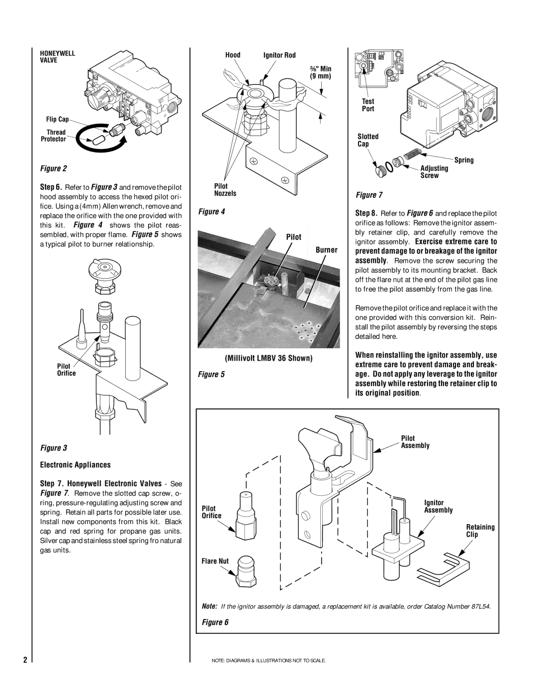
Step 8. Refer to Figure 6 and replace the pilot orifice as follows: Remove the ignitor assem- bly retainer clip, and carefully remove the ignitor assembly. Exercise extreme care to prevent damage to or breakage of the ignitor assembly. Remove the screw securing the pilot assembly to its mounting bracket. Back off the flare nut at the end of the pilot gas line to free the pilot assembly from the gas line.
Remove the pilot orifice and replace it with the one provided with this conversion kit. Rein- stall the pilot assembly by reversing the steps detailed here.
When reinstalling the ignitor assembly, use extreme care to prevent damage and break- age. Do not apply any leverage to the ignitor assembly while restoring the retainer clip to its original position.
2
Figure 3
Electronic Appliances
Step 7. Honeywell Electronic Valves - See Figure 7. Remove the slotted cap screw, o- ring,
Pilot
![]() Assembly
Assembly
Ignitor
PilotAssembly
Orifice
Retaining
Clip
Flare Nut
Note: If the ignitor assembly is damaged, a replacement kit is available, order Catalog Number 87L54.
Figure 6
NOTE: DIAGRAMS & ILLUSTRATIONS NOT TO SCALE.