ALL FIXED SETTING SIT VALVES
Millivolt Appliances
Step 9. SIT Systems - Refer to Figure 1. Using a Torx T20, or a flat screwdriver, remove and discard the three pressure regulator mounting screws. Remove the pressure regulator, spring, poppet, diaphragm and bushing.
Discard all removed components. Ensure the rubber gasket installed on the back of the replacement pressure regulator is properly positioned and install the new pressure regula- tor using the new screws supplied with this kit. Tighten screws to 25 In. lb. torque.
Step 10. Refer to Figure 3 and remove the pilot hood assembly to access the hexed pilot orifice. Using a (4mm) Allen wrench, remove and replace the orifice with the one provided with this kit. Figure 4 shows the pilot reas- sembled, with proper flame. Figure 5 shows a typical pilot to burner relationship.
Electronic Appliances
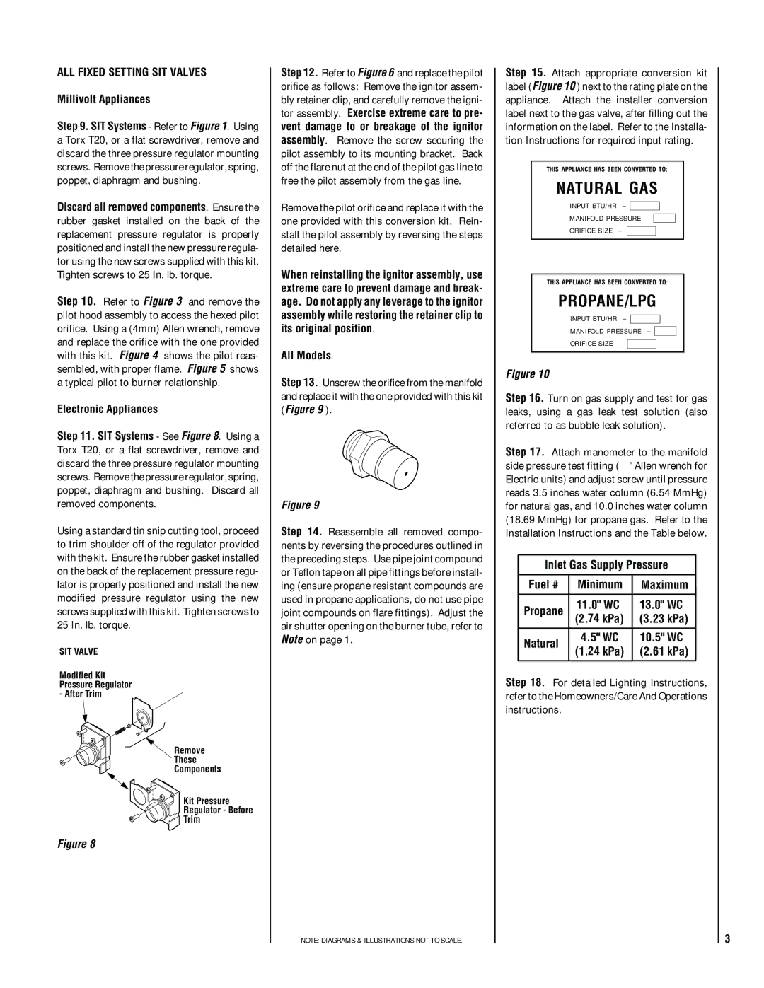
Step 11. SIT Systems - See Figure 8. Using a Torx T20, or a flat screwdriver, remove and discard the three pressure regulator mounting screws. Remove the pressure regulator, spring, poppet, diaphragm and bushing. Discard all removed components.
Using a standard tin snip cutting tool, proceed to trim shoulder off of the regulator provided with the kit. Ensure the rubber gasket installed on the back of the replacement pressure regu- lator is properly positioned and install the new modified pressure regulator using the new screws supplied with this kit. Tighten screws to 25 In. lb. torque.
SIT VALVE
Modified Kit
Pressure Regulator
- After Trim
Remove
These
Components
Kit Pressure
Regulator - Before
Trim
Figure 8
Step 12. Refer to Figure 6 and replace the pilot orifice as follows: Remove the ignitor assem- bly retainer clip, and carefully remove the igni- tor assembly. Exercise extreme care to pre- vent damage to or breakage of the ignitor assembly. Remove the screw securing the pilot assembly to its mounting bracket. Back off the flare nut at the end of the pilot gas line to free the pilot assembly from the gas line.
Remove the pilot orifice and replace it with the one provided with this conversion kit. Rein- stall the pilot assembly by reversing the steps detailed here.
When reinstalling the ignitor assembly, use extreme care to prevent damage and break- age. Do not apply any leverage to the ignitor assembly while restoring the retainer clip to its original position.
All Models
Step 13. Unscrew the orifice from the manifold and replace it with the one provided with this kit (Figure 9 ).
Figure 9
Step 14. Reassemble all removed compo- nents by reversing the procedures outlined in the preceding steps. Use pipe joint compound or Teflon tape on all pipe fittings before install- ing (ensure propane resistant compounds are used in propane applications, do not use pipe joint compounds on flare fittings). Adjust the air shutter opening on the burner tube, refer to Note on page 1.
NOTE: DIAGRAMS & ILLUSTRATIONS NOT TO SCALE.
Step 15. Attach appropriate conversion kit label (Figure 10 ) next to the rating plate on the appliance. Attach the installer conversion label next to the gas valve, after filling out the information on the label. Refer to the Installa- tion Instructions for required input rating.
THIS APPLIANCE HAS BEEN CONVERTED TO:
NATURAL GAS
INPUT BTU/HR –
MANIFOLD PRESSURE –
ORIFICE SIZE –
THIS APPLIANCE HAS BEEN CONVERTED TO:
PROPANE/LPG
INPUT BTU/HR –
MANIFOLD PRESSURE –
ORIFICE SIZE –
Figure 10
Step 16. Turn on gas supply and test for gas leaks, using a gas leak test solution (also referred to as bubble leak solution).
Step 17. Attach manometer to the manifold side pressure test fitting (¹⁄₄" Allen wrench for Electric units) and adjust screw until pressure reads 3.5 inches water column (6.54 MmHg) for natural gas, and 10.0 inches water column (18.69 MmHg) for propane gas. Refer to the Installation Instructions and the Table below.
Inlet Gas Supply Pressure
Fuel # | Minimum | Maximum |
|
| |||
|
|
|
|
Propane | 11.0" WC | 13.0" WC |
|
(2.74 kPa) | (3.23 kPa) |
| |
|
| ||
|
|
|
|
Natural | 4.5" WC | 10.5" WC |
|
(1.24 kPa) | (2.61 kPa) |
| |
|
| ||
|
|
|
|
Step 18. For detailed Lighting Instructions, refer to the Homeowners/Care And Operations instructions.
3