 Lenovo ideapad
 100S-14IBR Hardware Maintenance Manual
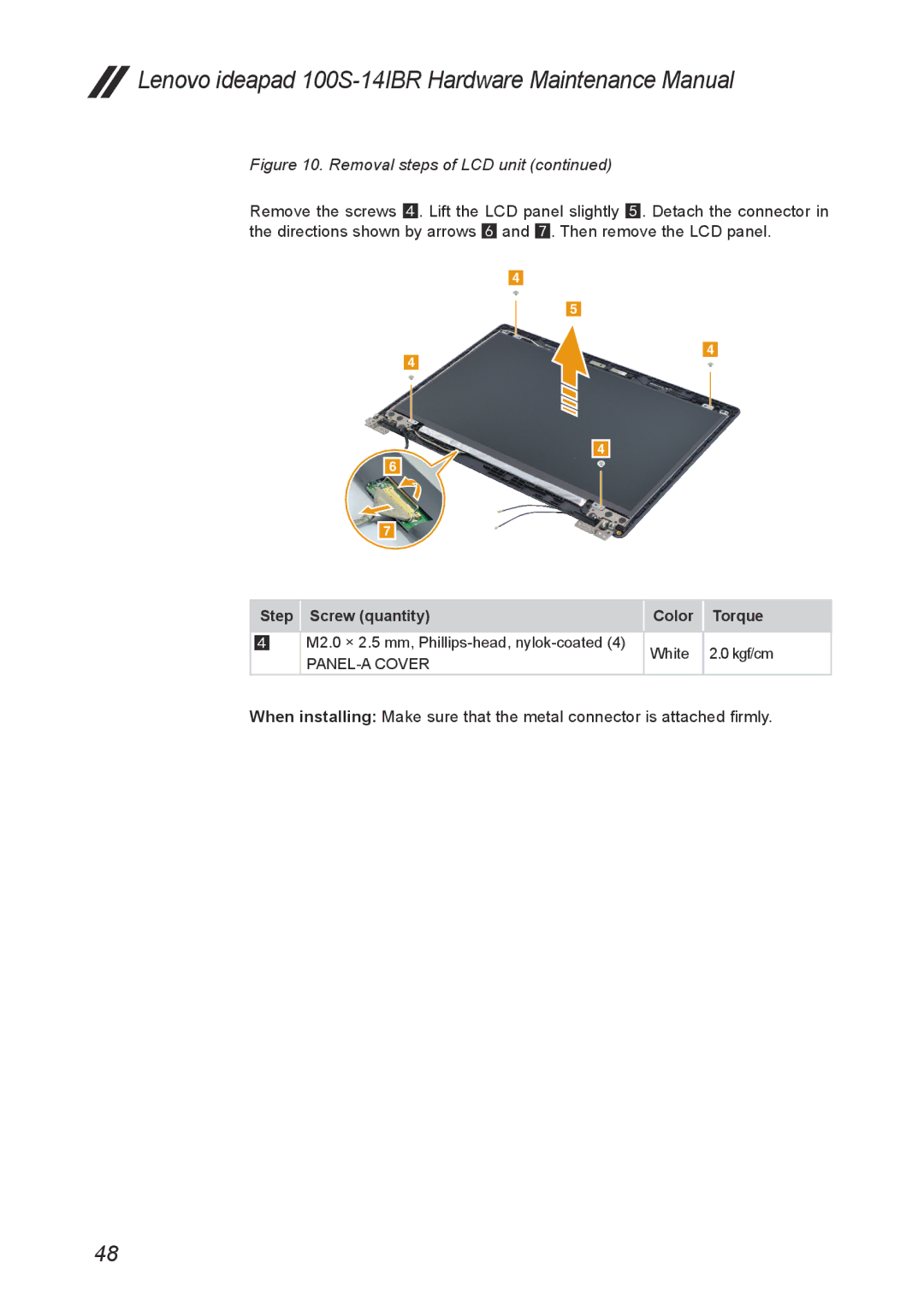
Figure 10. Removal steps of LCD unit (continued)
Remove the screws 4. Lift the LCD panel slightly 5. Detach the connector in the directions shown by arrows 6 and 7. Then remove the LCD panel.
4
5
4
4
4 6 ![]()
![]()
7
Step | Screw (quantity) | Color | Torque |
|
|
|
|
4 | M2.0 × 2.5 mm, | White | 2.0 kgf/cm |
|
| ||
|
|
|
When installing: Make sure that the metal connector is attached firmly.
48
