120 VAC Junction Box Kit (with surge protection)
Trousse de dérivation de 120 V c.a.
(avec limitation des surtensions transitoires)
Kit de Caja de Unión de 120 Vca (con supresión)
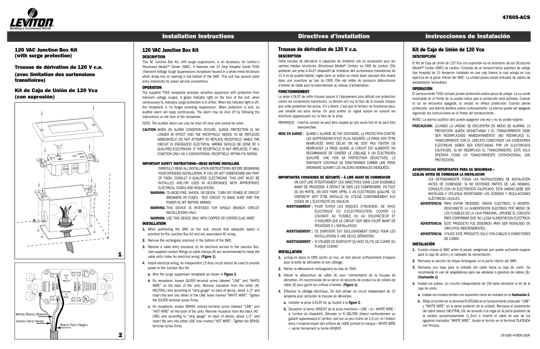
B |
A |
1 |
White/Blanc/Blanco |
Green/Vert/Verde |
Black/Noir/Negro |
2 |
Installation Instructions
120 VAC Junction Box Kit
DESCRIPTION
This AC Junction Box Kit, with surge suppression, is an accessory for Leviton’s Structured Media™ Center (SMC). It features one 15 Amp Hospital Grade TVSS (Transient Voltage Surge Suppression) receptacle housed in a white metal enclosure which drops into an opening in the bottom of the SMC. This unit has several cable entry knockouts for power service connections.
OPERATION
The supplied TVSS receptacle provides sensitive equipment with protection from transient voltage surges. A green indicator light on the face of the unit, when continuously lit, indicates surge protection is in affect. When the indicator light is off, the receptacle is no longer providing suppression. When protection is lost, an audible alarm will beep continuously. The alarm may be shut off by following the instructions on the face of the receptacle.
NOTE: The audible alarm can only be shut off once and cannot be reset.
CAUTION: WHEN AN ALARM CONDITION OCCURS, SURGE PROTECTION IS NO LONGER IN EFFECT AND THE RECEPTACLE NEEDS TO BE REPLACED IMMEDIATELY! DO NOT ATTEMPT TO REPLACE RECEPTACLE WHILE THE CIRCUIT IS ENERGIZED! ELECTRICAL WIRING SHOULD BE DONE BY A QUALIFIED ELECTRICIAN. IF THE RECEPTACLE IS NOT REPLACED, IT WILL FUNCTION ONLY AS A CONVENTIONAL RECEPTACLE WITHIN ITS RATING.
IMPORTANT SAFETY INSTRUCTIONS––READ BEFORE INSTALLING
CAREFULLY READ ALL INSTALLATION INSTRUCTIONS BEFORE BEGINNING YOUR INTENDED INSTALLATION. IF YOU DO NOT UNDERSTAND ANY PART OF THEM, CONSULT A QUALIFIED ELECTRICIAN. THIS UNIT MUST BE INSTALLED AND/OR USED IN ACCORDANCE WITH APPROPRIATE ELECTRICAL CODES AND REGULATIONS.
WARNING: TO AVOID FIRE, SHOCK, OR DEATH: TURN OFF POWER AT CIRCUIT BREAKERS OR FUSES. TEST CIRCUIT TO MAKE SURE THAT THE POWER IS OFF BEFORE WIRING!
WARNING: THIS DEVICE IS INTENDED FOR SINGLE BRANCH CIRCUIT INSTALLATIONS ONLY.
WARNING: USE THIS DEVICE ONLY WITH COPPER OR
INSTALLATION
1.When positioning the SMC on the wall, ensure that adequate space is provided for the Junction Box Kit and any associated AC wiring.
2.Remove the rectangular knockout in the bottom of the SMC.
3.Remove a cable entry knockout (A) for electrical service to the Junction Box.
4.Install electrical wiring. An independent 15 Amp circuit should be used to provide power to the Junction Box Kit.
a.Wire the surge suppressor receptacle as shown in Figure 2.
b.On receptacle, loosen SILVER terminal screw (labeled "LINE" and "WHITE WIRE" on the back of the unit). Remove insulation from the white (AC NEUTRAL) wire according to "strip gauge" on back of device, about 1/2" and insert the wire into either of the LINE holes marked "WHITE WIRE". Tighten the SILVER terminal screw firmly.
c.On receptacle, loosen BRASS colored terminal screw (labeled "LINE" and "HOT WIRE" on the back of the unit). Remove insulation from the black (AC LINE) wire according to "strip gauge" on back of device, about 1/2" and insert the wire into either LINE hole marked "HOT WIRE". Tighten the BRASS terminal screw firmly.
Directives d'installation
Trousse de dérivation de 120 V c.a.
DESCRIPTION
Cette trousse de dérivation à capacités de limitation est un accessoire pour les centres médias structurés (Structured MediaMC Center) ou CMS de Leviton. Elle présente une prise à DLST (dispositif de limitation des surtensions transitoires) de 15 A et de qualité hôpital, logée dans un boîtier en métal blanc pouvant être inséré dans une ouverture au bas du CMS. Elle est dotée de plusieurs débouchures d’entrée de câble pour le branchement au réseau d’alimentation.
FONCTIONNEMENT
La prise à DLST de cette trousse assure à l’équipement plus délicat une protection contre les surtensions transitoires. Le témoin vert sur la face de la trousse indique que cette protection est active. S’il s’éteint, c’est que le limiteur ne fonctionne plus; une tonalité est alors émise. On peut arrêter ce signal sonore en suivant les directives apparaissant sur la face de la prise.
REMARQUE : l’alarme sonore ne peut être coupée qu’une seule fois et ne peut être réenclenchée.
MISE EN GARDE : QUAND L’ALARME SE FAIT ENTENDRE, LA PROTECTION CONTRE LES SURTENSIONS N’EST PLUS ASSURÉE; LA PRISE DOIT ÊTRE REMPLACÉE SANS DÉLAI! ON NE DOIT PAS TENTER DE REMPLACER LA PRISE QUAND LE CIRCUIT EST ALIMENTÉ! ON RECOMMANDE DE CONFIER LE CÂBLAGE À UN ÉLECTRICIEN QUALIFIÉ. UNE FOIS SA PROTECTION DÉSACTIVÉE, LE DISPOSITIF CONTINUE DE FONCTIONNER COMME UNE PRISE ORDINAIRE SUIVANT LES VALEURS NOMINALES INDIQUÉES.
IMPORTANTES CONSIGNES DE SÉCURITÉ – À LIRE AVANT DE COMMENCER
ON DOIT LIRE ATTENTIVEMENT CES DIRECTIVES DANS LEUR ENSEMBLE AVANT DE PROCÉDER; À DÉFAUT DE BIEN LES COMPRENDRE, EN TOUT OU EN PARTIE, ON DOIT FAIRE APPEL À UN ÉLECTRICIEN QUALIFIÉ. CE DISPOSITIF DOIT ÊTRE INSTALLÉ OU UTILISÉ CONFORMÉMENT AUX CODES DE L’ÉLECTRICITÉ EN VIGUEUR.
AVERTISSEMENT : POUR ÉVITER LES RISQUES D’INCENDIE, DE CHOC ÉLECTRIQUE OU D'ÉLECTROCUTION, COUPER LE COURANT AU FUSIBLE OU AU DISJONCTEUR ET S’ASSURER QUE LE CIRCUIT SOIT BIEN COUPÉ AVANT DE PROCÉDER À L’INSTALLATION!
AVERTISSEMENT : CE DISPOSITIF EST EXCLUSIVEMENT CONÇU POUR LES INSTALLATIONS À UNE SEULE DÉRIVATION.
AVERTISSEMENT : N’UTILISER CE DISPOSITIF QU’AVEC DU FIL DE CUIVRE OU PLAQUÉ CUIVRE!
INSTALLATION
1.Lorsqu’on place le CMS contre un mur, on doit prévoir suffisamment d’espace pour la boîte de dérivation et son câblage.
2.Retirer la débouchure rectangulaire au bas du CMS.
3.Retirer la débouchure de câble (A) pour l’alimentation de la trousse de dérivation. On recommande de se servir de raccords de conduit ou de colliers de câble (B) pour garnir les orifices d’entrée. (Figure 1)
4.Effectuer le câblage électrique. On doit utiliser un circuit indépendant de 15 ampères pour alimenter la trousse de dérivation.
a.Installer la prise à DLST tel qu’illustré à la figure 2.
b.Desserrer la borne ARGENT de la prise (mentions « LINE » et « WHITE WIRE » à l’arrière du dispositif). Dénuder le fil NEUTRE (blanc) conformément au gabarit apparaissant à l’arrière, soit sur un peu moins de 1,5 cm, et l’insérer dans n’importe lequel des orifices de LIGNE portant la marque « WHITE WIRE »; serrer fermement la borne ARGENT.
Instrucciones de Instalación
Kit de Caja de Unión de 120 Vca
DESCRIPCIÓN
El Kit de Caja de Unión de 120 Vca con supresión es un accesorio de los Structured MediaMR Center (SMC) de Leviton. Consiste de un tomacorriente supresor de voltaje tipo Hospital de 15 Amperios instalado en una caja blanca la cual encaja en una apertura en la parte inferior del SMC. La unidad posee varias entradas de cables de alimentación removibles.
OPERACIÓN
El tomacorriente TVSS incluido provee protección contra picos de voltaje. La luz verde encendida en el frente de la unidad indica que la protección está activada. Cuando la luz se encuentra apagada, la unidad no ofrece protección. Cuando pierde protección, una alarma auditiva suena continuamente. La alarma puede ser apagada siguiendo las instrucciones en el frente del tomacorriente.
AVISO: La alarma auditiva sólo puede apagarse una vez y no se puede reponer.
PRECAUCION: ¡CUANDO LA UNIDAD SE ENCUENTRA EN MODO DE ALARMA, LA PROTECCIÓN QUEDA DESACTIVADA Y EL TOMACORRIENTE DEBE SER REEMPLAZADO INMEDIATAMENTE! ¡NO REEMPLACE EL TOMACORRIENTE CON EL CIRCUITO CONECTADO! LAS CONEXIONES ELÉCTRICAS DEBEN SER EFECTUADAS POR UN ELECTRICISTA CALIFICADO. SI NO REEMPLAZA EL TOMACORRIENTE, ESTE SOLO OPERARÁ COMO UN TOMACORRIENTE CONVENCIONAL (SIN PROTECCIÓN).
ADVERTENCIAS IMPORTANTES PARA SU SEGURIDAD –
LEALAS ANTES DE COMENZAR LA INSTALACION
LEA DETENIDAMENTE TODAS LAS INSTRUCCIONES DE INSTALACIÓN ANTES DE COMENZAR. SI NO ENTIENDE PARTES DE LAS MISMAS, CONSULTE CON UN ELECTRICISTA CALIFICADO. ESTA UNIDAD DEBE SER INSTALADA Y UTILIZADA RESPETANDO LOS CÓDIGOS Y REGULACIONES ELÉCTRICAS LOCALES.
ADVERTENCIA: PARA EVITAR INCENDIO, SHOCK ELECTRICO, O MUERTE: DESCONECTE LA ALIMENTACION ELECTRICA POR MEDIO DE LOS FUSIBLES EN LA CAJA PRINCIPAL. ¡PRUEBE EL CIRCUITO PARA CONFIRMAR QUE NO LLEGA ALIMENTACION ELECTRICA!
ADVERTENCIA: ESTE PRODUCTO FUE DISEÑADO PARA SER INSTALADO EN CIRCUITOS INDEPENDIENTES.
ADVERTENCIA: UTILICE ESTE PRODUCTO SOLO CON CABLES O CONECTORES DE COBRE.
INSTALACIÓN
1.Cuando coloca el SMC sobre la pared, asegúrese que quede suficiente espacio para la caja de unión y el cableado de alimentación.
2.Remueva la sección de chapa rectangular en la parte inferior del SMC.
3.Remueva una tapa para la entrada del cable hacia la caja de unión. Se recomienda el uso de adaptadores para las entradas o ganchos de cables (B).
(Ilustración 1)
4.Instale los cables. Un circuito independiente de 15A debe alimentar al kit de la caja de unión.
a.Instale los tomacorrientes con supresión como se muestra en la Ilustración 2.
b.Afloje el tornillo en la terminal PLATEADA en el tomacorriente (marcado “LINE” y “WHITE WIRE” en la parte posterior de la unidad). Remueva el aislamiento del cable blanco (NEUTRAL CA) de acuerdo a la regla en la parte posterior de la unidad, aproximadamente (1,3cm) e inserte el cable en uno de los agujeros marcados “WHITE WIRE”. Ajuste el tornillo en la terminal PLATEADA con firmeza.