Step 5b ![]() (no LED) Application:
(no LED) Application:
Step 5c ![]() Application:
Application:
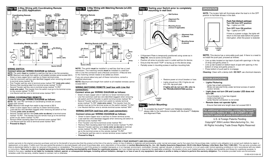
Step 6 Testing your Switch prior to completely ![]() mounting in wall box:
mounting in wall box:
OPERATION
Terminal
Coordinating RemoteSwitch Screw marked
White (WH)
Matching Remote
Terminal
Switch Screw marked White (WH)
Additional ![]() Neutral Wire
Neutral Wire
Wall Surface
Alignment Pin
NOTE: The locator light will illuminate when the load is in the OFF position to facilitate access in the dark.
![]()
![]() BL WH
BL WH![]()
3
YL/RD | RD |
| 5 |
2
1![]()
![]()
![]() 4
4
|
|
| 1 |
Terminal | BL | WH |
|
|
|
| |
Screw marked |
|
| 2 |
Black (BL) |
|
| |
|
|
| |
|
|
| 3 |
Terminal | YL/RD RD | 4 | |
Screw marked |
|
| 5 |
Yellow/Red |
|
| |
|
|
| |
(YL/RD) |
|
|
|
|
| Terminal | |
| Screw marked | ||
|
| Red (RD) | |
2
BL | WH |
| 1 |
| 4 |
| 3 |
YL/RD | |
5
4
Terminal | BL | WH | 2 |
Screw marked![]()
Black (BL)
|
| 3 |
Terminal | YL/RD RD | 1 |
Screw marked |
| 5 |
Yellow/Red |
| |
|
| |
(YL/RD) |
|
|
Terminal
Screw marked
Red (RD)
(2 places)
TOP
Mounting Screw (remove if applicable)
Alignment Hole
![]()
![]() TOP
TOP ![]()
![]() (2 places)
(2 places)
Push Pad (Default settings) Turn ON from OFF position:
Tap – Lights turn ON.
Turn OFF from ON position:
Tap – Lights turn OFF.
If there is a power outage, the lights will return to the last state before the power interruption, when the power is restored.
Coordinating Remote (no LED) |
| Switch | Matching Remote (with LED) |
| Switch | |||
WH | BL | WH | Hot (Black) | Hot (Black) | WH | BL | WH | BL |
| (unused) |
| BL | |||||
Green | Green |
|
|
|
|
| ||
|
| Green |
| Green |
| |||
Ground |
| Ground |
|
|
| Black | ||
Black |
|
|
|
| Ground |
| Ground | |
YL/RD |
| YL/RD |
|
| YL/RD | RD | YL/RD | |
RD | RD |
|
| |||||
| Line | Line |
|
|
| Load | ||
(unused) |
|
|
|
|
| |||
Load |
|
| 120VAC, 60Hz | 120VAC, 60Hz |
|
|
|
|
|
|
|
|
|
|
|
| |
Mounting Screw (2 places)
• If Alignment Plate is temporarily positioned using screw as in Step 4A, remove screw at this point.
Push | Locator |
Pad | Light |
NOTE: This device has a removable push pad. If there is a need to
White
Neutral (White)
WIRING SWITCH:
Connect wires per WIRING DIAGRAM as follows:
NOTE: The switch must be installed in a wall box that has a Line Hot connection.
NOTE: Maximum wire length from switch to all installed remotes cannot exceed 300 ft.
•Green or bare copper wire in wall box to Green terminal screw.
•Line Hot (common) wall box wire identified (tagged) when removing old switch to terminal screw marked “BL”.
•First Traveler wall box wire to terminal screw marked “RD” (note wire color).
•Remove Red insulating label from terminal screw marked “YL/RD”.
•Second Traveler wall box wire to terminal screw marked “YL/RD”
(note wire color). This traveler from the switch must go to the terminal screw on the remote marked “YL/RD”.
•Line Neutral wall box wire to terminal screw marked “WH”.
WIRING COORDINATING REMOTE:
Connect wires per WIRING DIAGRAM as follows:
NOTE: "BL" and "RD" terminals on coordinating remote are unused. Tighten both screws.
NOTE: Maximum wire length from switch to last remote is 300 ft.
•Green or bare copper wire in wall box to Green terminal screw.
•Load wall box wire identified (tagged) when removing old switch to First Traveler (note color as above).
•Second Traveler wall box wire (note color as above) to terminal screw marked "YL/RD". This traveler from the remote must go to the terminal screw on the switch marked "YL/RD".
•Remove White insulating label from terminal screw marked "WH".
•Line Neutral wall box wire to terminal screw marked "WH".
•Proceed to Step 6.
White
Neutral (White)
NOTE: The switch must be installed in a wall box that has a Load connection. The matching remote must be installed in a wall box with a Line Hot connection and a Neutral connection. A Neutral wire to the matching remote needs to be added as shown.
If you are unsure about any part of these instructions, consult a qualified electrician.
NOTE: Maximum wire length from switch to all installed remotes cannot exceed 300 ft.
WIRING MATCHING REMOTE (wall box with Line Hot connection):
Connect wires per WIRING DIAGRAM as follows:
•Green or bare copper wire in wall box to Green terminal screw.
•Line Hot (common) wall box wire identified (tagged) when removing old switch and First Traveler to switch terminal screw marked "BL".
•Second Traveler wall box wire from switch to remote terminal screw marked "YL/RD" (note wire color). This traveler from the remote must go to the terminal screw on the switch marked "YL/RD".
•Line Neutral wall box wire to remote terminal screw marked "WH".
WIRING SWITCH (wall box with Load connection):
Connect wires per WIRING DIAGRAM as follows:
•Green or bare copper wire in wall box to Green terminal screw.
•Load wall box wire identified (tagged) when removing old switch to terminal screw marked "RD".
•First Traveler Line Hot to terminal screw marked "BL".
•Remove Red insulating label from terminal screw marked "YL/RD".
•Second Traveler wall box wire (note color as above) to terminal screw marked "YL/RD". This traveler from the switch must
go to the terminal screw on the remote marked "YL/RD".
•Line Neutral wall box wire to remote terminal screw marked "WH".
•Proceed to Step 6.
• Position all wires to provide room in outlet wall box for device.
• Ensure that the word "TOP" is facing up on the device strap.
• Partially screw in mounting screws in wall box mounting hole.
P | TOP |
TO |
|
• Restore power at circuit breaker or fuse.
• Lights should turn ON. If lights do not turn ON, tap push pad.
If lights still do not turn ON, refer to the TROUBLESHOOTING section.
Locator
Light
Step 7 Switch Mounting:
To complete the Acenti™ Switch and Wallplate installation,
please refer to the instructions included with the Acenti™ Wallplate and Alignment Plate.
•Line up tabs located on top back of pad with openings in the top of strap and gently press in.
•Line up tab located on bottom back of pad with opening in the bottom of strap and gently press in.
•Press bottom of push pad to
Cleaning: Clean with a damp cloth. DO NOT use chemical cleaners.
TROUBLESHOOTING
•Lights Flickering
-Lamp has a bad connection.
-Wires not secured firmly under terminal screws of switch and/or remote.
•Light does not turn ON and Locator LED does not turn ON
-Circuit breaker or fuse has tripped.
-Lamp is burned out.
-Lamp Neutral connection is not wired.
•Remote does not operate lights
-Ensure that total wire length does not exceed 300 ft.
For additional information, contact the Acenti™ Information Hotline at
U.S. & Foreign Patents Pending
Copyright© 2004 Leviton Manufacturing Co., Inc. All Rights Including Trade Dress Rights Reserved
LIMITED 5 YEAR WARRANTY AND EXCLUSIONS
Leviton warrants to the original consumer purchaser and not for the benefit of anyone else that this product at the time of its sale by Leviton is free of defects in materials and workmanship under normal and proper use for five years from the purchase date. Leviton’s only obligation is to correct such defects by repair or replacement, at its option, if within such five year period the product is returned prepaid, with proof of purchase date, and a description of the problem to Leviton Manufacturing Co., Inc., Att: Quality Assurance Department,