Manuals
/
Leviton
/
Computer Equipment
/
Switch
Leviton
HCC4D
installation instructions
Wall Mounted Controller, Installation Instructions, Snaps
Models:
HCC4A
HCC3D
HCCS7
HCC2D
HCC4D
1
1
2
2
Download
2 pages
10.79 Kb
1
2
Install
Wiring Diagram
Page 1
Image 1
Page 1
Page 2
Page 1
Image 1
Page 1
Page 2
Contents
WALL MOUNTED CONTROLLER
INSTALLATION INSTRUCTIONS
Cat. Nos
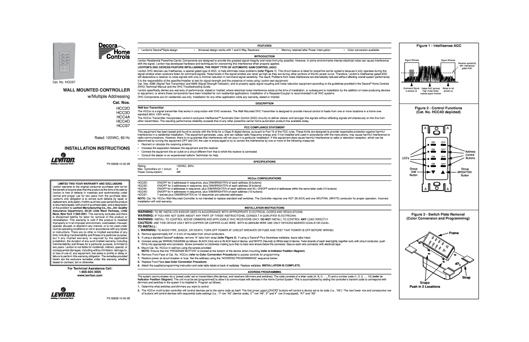
Figure 2 - Control Functions Cat. No. HCC4D depicted
Indicator Position Diagram
Unit Code Settings
House Code Settings
Wiring Diagram
Top
Page
Image
Contents