LCD TV / LED LCD TV
Separate purchase
Wireless Media Box
Contents
Contents
Power Cord
Accessories
Preparation
Polishing Cloth
Speaker
Front Panel Controls
Back Panel Information
USB Input
Only 26LD35**, 26LD34
HDMI/DVI in Input
Power Cord Socket
RGB/DVI Audio Input
Euro Scart Socket AV1
Only 26/32LD35**, 26/32LD34
Stand Installation
Only 19/22LD35**, 19/22LD34
Only 19/22LD35**, 19/22LD34 Only 26/32LD35 , 26/32LD34
Not Using the DESK-TYPE Stand
Carefully place the TV screen side down
Detach the stand from TV
External Equipment Setup section
Back Cover for Wire Arrangement
Open the Cable Management Clip as
Shown
Only 19/22LD35**, 19/22LD34
Swivel Stand
Attaching the TV to a
System
Mounting bracket when mounting the TV to a
Installation
Earthing
We recommend the use of a LG Brand wall
Subtitle Recalls your preferred subtitle in digital mode
Remote Control KEY Functions
Installing Batteries
Only 32/37
Bolts for stand assembly
AAA
Only 32/37/42/47LD45
Only 26LD32**, 26LD33
Input Power
Back Panel Information
Screen from damage Assemble the TV as shown
Attaching the TV to a Desk
Not Using DESK-TYPE Stand
Open the Cable Management Clip as shown
Fit the Cable Management Clip as shown
Product to the wall as shown in the picture
Use the eye-bolts or TV brackets/bolts to fix
200 26/32LD32 26/32LD33
32LD4 200
Remote Control KEY Functions
Installing Batteries
Only 32/42LD5
Remote Control
Preparation Speaker
Wireless Control
Assemble the TV as shown
Attaching the TV to a
Kensington Security System
32LD5 200 42LD5 46LD5 52LD5 400 60LD5
Audio or Audio Language, Sleep Timer, Skip Off
Ratio, Clear Voice II , Picture Mode, Sound Mode
Adjust the system settings to your preference
Returns to the previously viewed programme
Installing Batteries
Power plug, the better it is
Only 26LE3 26LE5 Bolts for stand assembly
Use on the screen. scratching or discolou- ration
M4x14 M4x20
Touch Sensor
Only 19/22LE3***, 22LE5
Connect to the power cord socket
Only 26LE3***, 26LE5
Only 32LE3***, 32/37/42LE4***, 32/37/42/47/55LE5
Only 19/22LE3***, 22LE5
Fix the 4 bolts securely using the holes
Cover with the TV
Back of the TV
Only 19/22/26LE3***, 22/26LE5
Connection of TV
Kensington Security System
32LE3
19/22/26LE3
32LE4
37/42LE4
Remote Control KEY Functions
Installing Batteries
Wall Antenna Socket Outdoor
External Equipment Setup
Antenna Connection
Component in Audio jacks on the TV
Connecting with a Component Cable
Component Input ports
Connecting with AN Hdmi Cable
Connecting with AN Hdmi to DVI Cable
AV1
Connecting with a Euro Scart Cable
Connecting with a RF Cable
USB Setup
Appropriate channel between the TV
VCR for viewing Wall Jack Antenna
Connecting with a RCA Cable
Select RGB input source using the Input but
Connecting with a D-SUB 15 PIN Cable
PC jack on the TV
Connect the PC audio output to the Audio
To adjust the headphone volume, press
Headphone Setup
Insertion of CI Module
Check this point as shown and insert the CI Module
Digital Audio OUT Setup
Wireless Control jack and HDMI/DVI
External Equipment Wireless Connection
RGB-PC, HDMI/DVI-PC mode
Supported Display Resolution
HDMI/DVI-DTV mode
Setup
Screen Reset
Screen Setup for PC Mode
Select Picture Select Screen Select Reset Select Yes
Run Reset
Auto configure
Auto Configure RGB PC mode only
Select Auto Config
Run Auto Config
Select the desired resolution
Selecting Resolution
Select Resolution
Make appropriate adjustments
Adjustment for screen Position, Size, Phase
Select Position, Size or Phase
Volume Adjustment
Initializing Setup
Turning on the TV
Programme Selection
Watching TV
Quick Menu
Audio or Audio Language Selects the sound output
Programme Control
32/37/42/47LD425, 32/37/42/47LD426, 26/32LD335, 26/32LD336
On Screen Menus Selection and Adjustment
Control
Select Setup
Auto Programme Tuning
Select Auto Tuning
Run Auto tuning
Watching
Setup -Auto Tuning -Cable -Setting
Select Cable
Select Comhem or Other Operators
Quick
When you select the Quick
Select Full Select OK Select Start
When you select the Full
Watching TV / Programme Control
Watching TV / Programme
Cable DTV Setting
Select Manual Tuning
Manual Programme Tuning
Select Manual Tuning Select Cable DTV
Commence searching
Select Setup Select V/UHF or Cable
Channel number
Select Name
Fine Tuning
Assigning a station name
Skipped
Programme Edit
Select Programme Edit Enter the Programme Edit
TV Mode
DTV/RADIO Mode
Selecting favourite programme
Auto Sort
After activating Auto Sort once, you can no
Start Auto Sort Longer edit programmes
Selecting favourite programme group
Information, language, or software download etc Save
CI Common Interface Information
Select CI Information
Programme
Software Update
RED Select Customer Support Select Software Update
When setting Software Update
Select Yes or No
PICTURE/SOUND Test
Select Signal Test
Diagnostics
RED Select Customer Support
Software Version
RED Select Customer Support Select Product/Service Info
PRODUCT/SERVICE Information
Select the part of the manual you want to see
Simple Manual
Select Simple Manual
Displaying programme List
Selecting the Programme List
Selecting a programme in the programme list
Display the Programme List
Return to normal TV viewing
Paging through a programme list
Turn the pages
Currently selected Group Favourite group is changed
Input List
Selects a label for each input source
Input Label
Blue Select Input Label
Select the source Select the label
Select Option
Data Service
Select Data Service Select Mheg or Teletext
Display the Simplink Select On or Off Save
Simplink
Connect the HDMI/DVI in 1, Hdmi
Connecting to Home Theater with the Simplink logo
Simplink Functions
Simplink Menu
Game Optimizes video and audio for playing games
AV Mode
Select Factory Reset
Initializingreset to Original Factory Settings
To USE a USB Device
When Connecting a USB Device
Select the USB Device menu before removing the USB device
Select USB Device
Precautions when using the USB device
Movie List
To USE a USB Device
MPEG1, MPEG2
Screen Components
You can also adjust USB in the Input menu
To USE
Select Movie List
When playing movie files
Using the remote control
Blue Convert to Mark Mode
Movie Selection
Mark Mode
When selected movie files are played
Play the selected movie file
Blue Exit the Mark Mode
Mark all movie files on the screen
Yellow Deselect all marked movie files
Select Set Video Play., Set Video. or Set Audio
Using the Movie List function, play
Or Show the Option menu
Energy Saving
Subtitle Langugae or Repeat
When you select the Set Video Play
Select Picture Size, Audio Language
Select Picture Mode or TruMotion
When you select the Set Video
Balance
When you select the Set Audio
Select Photo List
Photo List
You can view photo files on USB storage device
Select the desired photos Photo files are displayed
When playing photo files
Photo Selection
Convert to Mark Mode
When selected photo files are displayed
Select the target folder or drive
Mark desired photo file
Yellow Deselect all marked photo files
Display the selected photo file
Mark all photo files on the screen
How to view photo
Zoom
Slideshow
Option, Hide or
Exit
Using the Photo List function
Select Slide Speed or BGM
When you select the Set Photo View
Make appropriate adjustments. Refer to p to103
When you select the Set Audio
Music List
Contents under the folder
Select Music List
Corresponding buttons on
Music Selection
When playing music files
To USE a USB
Device
When selected music files are played
Yellow Deselect all marked music files
Display the selected music file
Mark all music files on the screen
Files Marked
Using the Music List function, play
Be played
Screen.Refer to p
Select Repeat or Random
When you select the Set Audio Play
When you select the Set Audio
002. B02.mp3 0031
Display DivX Reg. Code
Divx Registration Code
Display Deactivation
Deactivation
Shows current programme information
EPG Electronic Programme Guidein Digital Mode
Select a programme
Switch on/off EPG
Button Function in NOW/NEXT Guide Mode
EPG Electronic Programme Guide
Button Function in Extended Description Box
Button Function in Date Change Mode
Save Timer Record/Remind
Button Function in Record/Remind Setting Mode
Switch off Schedule List
Button Function in Schedule List Mode
Select your desired OptionModify/Delete/ Delete All
Select programme Up/Down
Select Aspect Ratio
Picture Size Aspect Ratio Control
169 Original
Just Scan
Cinema Zoom
149
Select input source to apply the settings
Select Picture Wizard Adjust StandardBlack Level
Picture Wizard
Select Picture
Select Energy Saving
Energy Saving
Select AutoOnly 32/42/46/52/60LD5***, 32LE3***, 32/37/42LE4
Off
Picture Mode-Preset
Preset Picture Settings
Select Picture Mode
32LE3***, 32/37/42LE4***, 32/37/42/47/55LE5
Picture Mode-User option
Manual Picture Adjustment
Select your desired Source
Picture Improvement Technology
Select Advanced Control
Expert
Expert Picture Control
100
101
Select Picture Reset
Picture Reset
Initialize the adjusted value
102
Select TruMotion Select Low, High, User or Off
Trumotion
Power Light
Power Indicator
Select Power Indicator Select Standby Light or Power Light
104
105
Mode Setting
Select Mode Setting Select Store Demo or Home Use
Select Mode Setting Select Store Demo
Demo Mode
106
Select On
Select Auto Volume
Auto Volume Leveler
107
Select Audio
Clear Voice
Adjustment for Clear Voice Level With selecting On
108
Select Clear Voice
109
Preset Sound SETTINGS-SOUND Mode
Select Audio You can also adjust Sound Mode in the Q
Select Sound Mode
Sound Setting Adjustment -USER Mode
Infinite Sound
110
111
Select Audio Select Balance Make desired adjustment
Balance
Select TV Speaker
TV Speakers ON/ OFF Setup
112
113
DTV Audio Setting in Digital Mode only
114
Selecting Digital Audio OUT
Select Digital Audio Out
Select Auto or PCM
115
Audio Reset
Select Audio Select Reset
Adjustment for Audio Description Volume With selecting On
Audio Description in Digital Mode only
Select Volume or Beep Make desired adjustment
116
Select Audio or Audio Language
117
Select the sound output
Mono sound selection
Nicam Dual I+II or FM Mono
118
119
ON-SCREEN Menu Language / Country Selection
Select LanguageLanguage
Select Menu Language
120
Language Selection
Select Hard of Hearing
Select your desired language
Audio Language Selection
121
Select an audio language
Subtitle Language Selection
Time Setting
Clock Setup
122
Select Time
Setting
Auto ON/OFF Time Setting
123
Select Off Time or On Time
124
Sleep Timer Setting
125
SET Password & Lock System
Select Lock System
Parental
126
Block Programme
Enter the Block Progra mme Enter the Block Programme
Yellow Select a programme to be locked
127
Parental Control in Digital Mode only
Select Lock System Select Parental Guidance
Parental Control / Ratings
128
External Input Blocking
Select Lock System Select Input Block
Select input source Select On or Off
129
KEY Lock
This feature is not available in all countries
Switch ON/OFF
Simple Text
130
Fastext
TOP Text
131
Block / group / page selection
132
Special Teletext Functions
Teletext in Digital Service
Teletext Within Digital Service
133
This function works in UK, Ireland only
134
Troubleshooting
Appendix
Hdmi
Audio function does not work
135
Cleaning the Screen
Maintenance
Cleaning the Cabinet
Extended Absence
137
Product Specifications
32LD4
138
42LD4
139
32LD5 32LD550-ZC / 32LD550N-ZC
140
46LD5 46LD550-ZC / 46LD550N-ZC
141
60LD5 60LD550-ZC / 60LD550N-ZC
142
42LE4 42LE4500-ZA / 42LE4500N-ZA 42LE4508-ZA
143
19LE340N-ZA / 19LE3408-ZA
144
26LE3
145
37LE5
146
47LE5
147
148
IR Codes
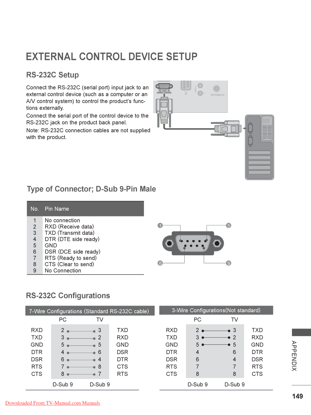
RS-232C Setup
External Control Device Setup
Type of Connector D-Sub 9-Pin Male
RS-232C Configurations
150
Set ID
151
Command Reference List
Communication Parameters
Power Command k a
153
Tint Command k j
154
Energy Saving Command j q
155
KeyCommand m c
DirectFB, glibc, gconv
Open Source Software Notice
156
157
Version 2, June
Open Source License
158
159
160
161
162
GNU Lesser General Public License
163
164
165
166
167
Mozilla Public License
168
169
170
10. U.S. Government END Users
Model Serial No