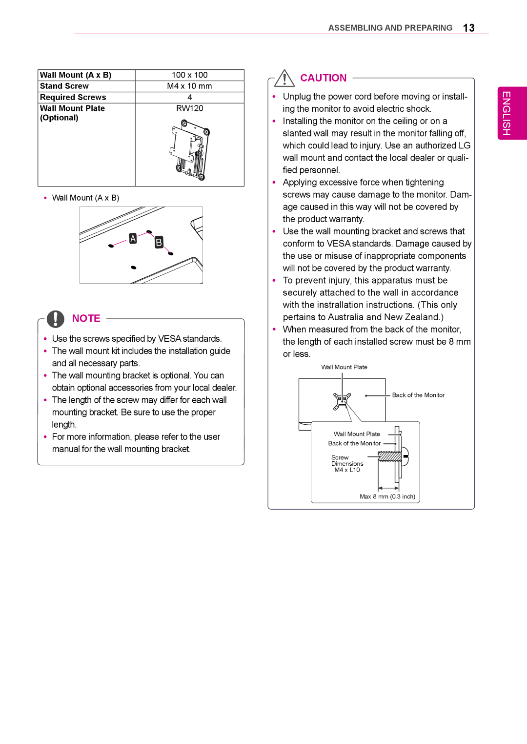
34UM95-PD/ 34UM95-PE / 34UM94-PD specifications
LG Electronics has made significant strides in the monitor market with its 34UM95-PD, 34UM95-PE, and 34UM94-PD models, designed to cater to both professional and casual users seeking optimal visual performance. These ultrawide monitors showcase LG's commitment to delivering high-quality displays that enhance productivity and provide an immersive experience.One of the standout features of these monitors is their 34-inch IPS display, which offers a resolution of 3440 x 1440 pixels. This high resolution ensures sharp images and clarity, making it ideal for creative professionals, gamers, and anyone who spends long hours in front of a screen. The ultra-wide aspect ratio of 21:9 expands the field of view, allowing users to multitask efficiently by having multiple windows open side by side without compromising the visibility of each.
Another key characteristic is the extensive color accuracy that the 34UM95 and 34UM94 series provide. These monitors cover over 99% of the sRGB color spectrum, enabling vivid and true-to-life colors. This feature is particularly beneficial for graphic designers, photographers, and videographers, where color precision is critical. Additionally, the monitors support HDMI and DisplayPort inputs, making them versatile for various devices.
Moreover, the integration of LG's advanced technology enhances the overall visual experience. The monitors come equipped with Thunderbolt 2, which offers lightning-fast data transfer and connectivity, making them perfect companions for MacBook users and creative professionals. The split-screen function allows users to divide the screen into multiple sections, which further boosts productivity by enabling seamless multitasking.
User comfort is also a significant consideration. The ergonomic design of these monitors allows for height adjustment, tilt, and swivel, ensuring that users can find their most comfortable viewing position. The sleek design, coupled with narrow bezels, gives the monitors a modern and elegant look that fits perfectly in any workspace.
Overall, the LG 34UM95-PD, 34UM95-PE, and 34UM94-PD monitors combine cutting-edge technology, superb color accuracy, and ergonomic design to provide a premium viewing experience. Whether for professional use or personal entertainment, these monitors are well-suited to meet the diverse needs of today's users, making them a worthy investment in high-quality display technology.

