Manuals
/
LG Electronics
/
TV and Video
/
Flat Panel Television
LG Electronics
42CS560-ZD Total Assembly line process, Function Check, Adjustment Preparation
Models:
42CS560-ZD
1
11
41
41
Download
41 pages
48.94 Kb
8
9
10
11
12
13
14
15
Troubleshooting
Specifications
Diagram
Signal TABLE
Total Assembly line process
Adjustment Instruction
IC Remove/Replacement
Safety Precautions
Normal Power
http//aic.lgservice.com
Page 11
Image 11
Page 10
Page 12
Page 11
Image 11
Page 10
Page 12
Contents
http//eic.lgservice.com
CHASSIS LD01M
READ THE SAFETY PRECAUTIONS IN THIS MANUAL
http//aic.lgservice.com
SPECIFICATION
CONTENTS
CONTENTS
PRODUCT SAFETY
Before returning the receiver to the customer
SAFETY PRECAUTIONS
IMPORTANT SAFETY NOTICE
General Guidance
Electrostatically Sensitive ES Devices
SERVICING PRECAUTIONS
Power Output, Transistor Device Removal/Replacement
IC Remove/Replacement
Replacement
Small-Signal Discrete Transistor Removal/Replacement
3. Test method
SPECIFICATION
4. Model General Specification
1. Application range
6. RGB Input PC
5. Component Video Input Y, CB/PB, CR/PR
2 PC Mode
7. HDMI Input PC/DTV
1 DTV Mode
3. Main PCB check process
ADJUSTMENT INSTRUCTION
1. Application Range
2. Designation
After downloading, have to adjust Tool Option again
3.1. ADC Process
3.2. EDID Download
3.3. EDID data
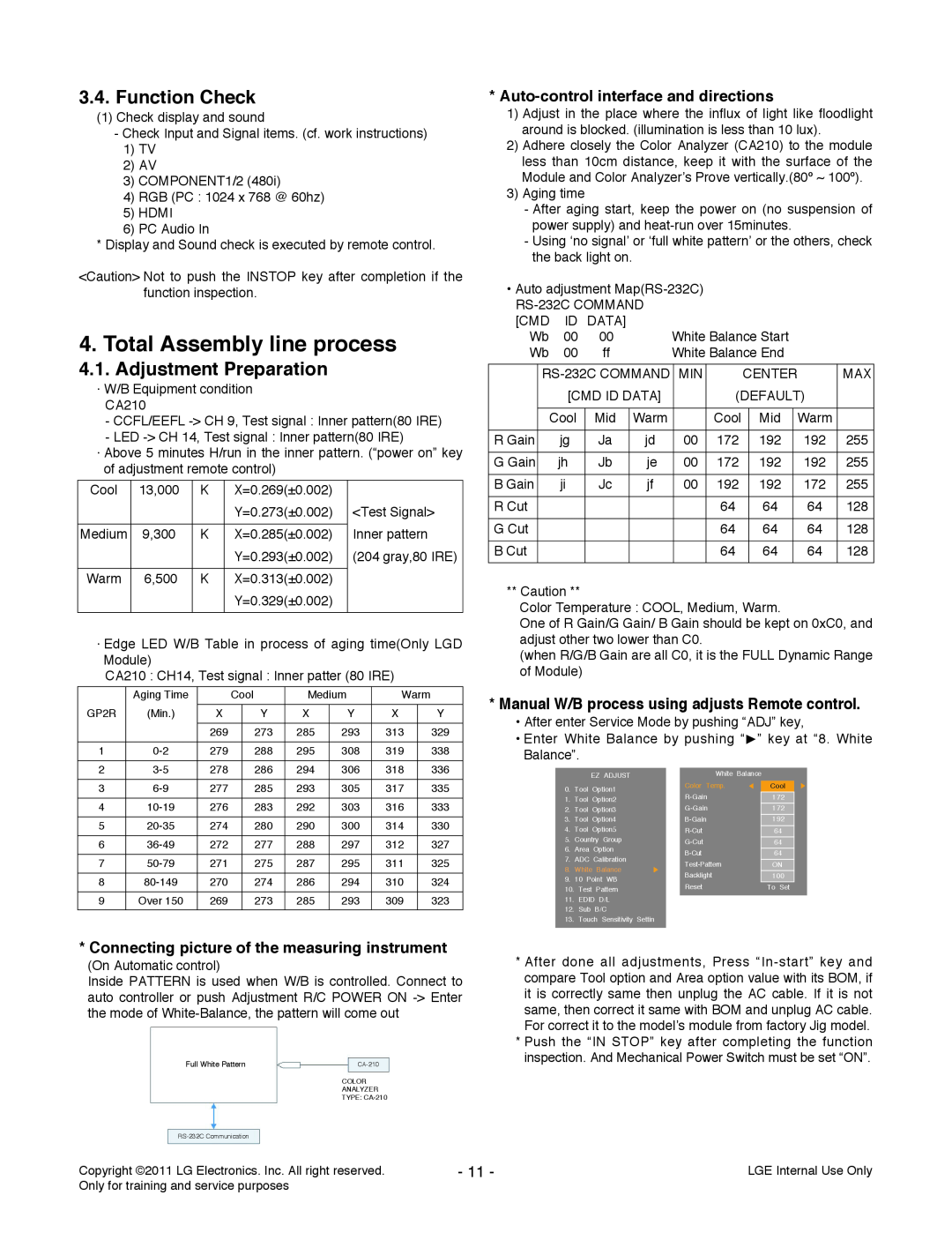
Manual W/B process using adjusts Remote control
4. Total Assembly line process
4.1. Adjustment Preparation
3.4. Function Check
5. GND and HI-POT Test
4.3. Outgoing condition Configuration
6.1. Signal TABLE
6.2. Command Set
7. CI+ Key Download method
No No No No No
TROUBLESHOOTING
1. Power-up boot check
No No No No
2. Digital TV Video
3. Analog TV Video
ok No
4. AV Video
5. Component Video
No No No
7. RGB Video
6. SCART Video
Check HDMI Cable conductors for damage or open conductor
8. HDMI Video
9. All Source Audio
11. Analog TV Audio
10. Digital TV Audio
14. RGB Audio
12. AV Audio
13. Component/ SCART Audio
Option
DIAGRAM
Side
Rear
EXPLODED VIEW
LGE Internal Use Only
Only for training and service purposes
GP3S7LR
Copyright 2012 LG Electronics. Inc. All rights reserved
DDR3
Normal Power
VDDC
Normal
+1.5VDDR
FROM LIPS & POWER B/D
PowerDET
+3.3VNormal
CONTROL IR & LED
IC1450
USBDIODES
GP3S7LR20110324 HDMI8
HDMI EEPROM
HDMI1
SIDEHDMI
RGB/SPDIF/PC/HP
New Item Development
GP3S7LR RS232C9PIN
RS232C
FILRE AND ELECTRICAL SHOCK HAZARDS, WHEN SERVICING IF IS
K4B1G1646G-BCH9
GP3S7LR DDR256
DDR3 1.5V By CAP - Place these Caps near Memory
IC1201-*1
IC1401-*1
GP3S7LR SFLASH
GP4RGLOBALTUNERBLOCK
GP3S7LR
20110511
TUNERL
IC501 NTP-7400L
GP3S7LR NTP7400
GP3S7LR REAR JACK
Full Scart/ Comp1
SIDE COMPONENT PHONE JACK New Item Developmen
10067972-0500LF
CI Region
Option name of this page CISLOT because of Hong Kong
GP3S7LR PCMCI
20110324
GASKET
SMD GAS
GP3 S7LR
Top
Page
Image
Contents