Downloaded From | Copyright C 2008 LGElectronics Only for training and service |
1. Power Board
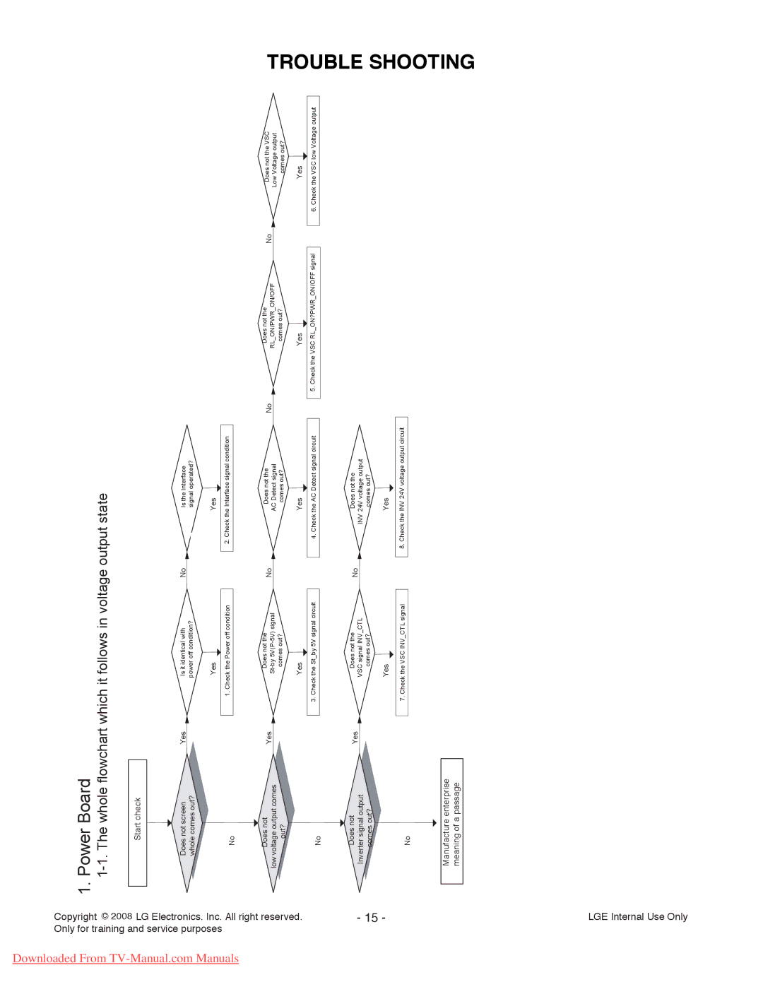
1-1. The whole flowchart which it follows in voltage output state
Start check
com Manuals | . Inc. All right purposes |
| reserved. |
Does not screen | Yes | |
whole comes out? |
| |
No |
| |
Does not | Yes | |
low voltage output comes | ||
| ||
| ||
out? |
| |
No |
|
Is it identical with power off condition?
Yes
1. Check the Power off condition
Does not the
comes out?
Yes
3. Check the St_by 5V signal circuit
No | Is the Interface |
| signal operated? |
Yes
2. Check the Interface signal condition
No | Does not the | |
AC Detect signal | ||
| ||
| ||
| comes out? |
Yes
4. Check the AC Detect signal circuit
No | Does not the | No | |
RL_ON/PWR_ON/OFF | |||
|
| ||
| comes out? |
|
Yes
5. Check the VSC RL_ON?PWR_ON/OFF signal
Does not the VSC Low Voltage output comes out?
Yes
6. Check the VSC low Voltage output
TROUBLE
- 15 -
Does not | Yes | |
Inverter signal output | ||
| ||
comes out? |
|
No
Manufacture enterprise meaning of a passage
Does not the VSC signal INV_CTL
comes out?
Yes
7. Check the VSC INV_CTL signal
No | Does not the |
| INV 24V voltage output |
| comes out? |
Yes
8. Check the INV 24V voltage output circuit
SHOOTING
LGE Internal Use Only
