http//aic.lgservice.com
READ THE SAFETY PRECAUTIONS IN THIS MANUAL
http//eic.lgservice.com
http//biz.lgservice.com
SAFETY PRECAUTIONS
CONTENTS
SERVICING PRECAUTIONS
SPECIFICATION
IMPORTANT SAFETY NOTICE
SAFETY PRECAUTIONS
Electrostatically Sensitive ES Devices
SERVICING PRECAUTIONS
Replacement
IC Remove/Replacement
Small-Signal Discrete Transistor Removal/Replacement
Removal
4. Model General Specification
SPECIFICATION
1. Application range
3. Test method
RGB-PC
RGB Input
AnalogD-SUB 15PIN
HDMI1-DTV/DVI
5.2. RGB Input PC
5. Video resolutions 2D
5.1. Component Input Y, CB/PB, CR/PR
PCDVI
5.3. HDMI InputPC/DTV
Boot file Download
ADJUSTMENT INSTRUCTION
After downloading, have to adjust Tool Option again
1. Application Range
4.1. Adjustment Preparation
4. Total Assembly line process
3.1. ADC Process
3.2. Function Check
4.2. DDC EDID Write RGB 128Byte
4.4. EDID data
4.3 DDC EDID Write HDMI 256Byte
Manual W/B process using adjust Remote control
4.6. HI-POT Test
4.5. Outgoing condition Configuration
4.6.1. HI-POT auto-check preparation
4.6.2. HI-POT auto-check
5. Model name & Serial number D/L
5.1. Signal Table
5.2. Comand Set
5.3. Method & notice
CI+ Key Value
6.1. Download Procedure
6. CI+ Key Download method
S7LR
BLOCK DIAGRAM
All rights reserved
Half
EXPLODED VIEW
GP4MSTAR
EMEA INTERACTIVE
2011 . 08
Copyright 2012 LG Electronics. Inc. All rights reserved
OLED
THERMAL
Step Up regulator 3 . 3V to 5VMAX 250mA
PowerDET
FROM LIPS & POWER B/D
+1.5VDDR
+3.3VNormal
NTP-7500L
IC501
CONTROL IR & LED
30Pin LVDS Connector For HD 60HzNormal
51Pin LVDS Connector
For FHD 60/120Hz
MIRROR Pol - change
For CEC
HDMI1
HDMI2
SIDEHDMI
0 . 3 3 u F
USBDIODES
RGB/SPDIF/PC/HP/USB
S7LRDIVXMS10
MX25L8006EM2I-12G
IC1300
IC1300-*1
W25Q80BVSSIG
SI2156DVB1INPUTH
P4RGLOBALTUNERBLOCK
SI2176ATSC1INPUTH
PILG1001 A2
IC1501
LGDT1001
Full Scart/ Comp1
EXTSPK AMP
UART/I2C SWITCH
EXTSPKCONTROL/DEBUG
EXTSPK OUT
REAL TIME CLOCKRTC
EXTERNALPOWER OUT 5V/12V
Option name of this page CI SLOT because of Hong Kong
CI Region
SMD GASKET
Page
1. Trouble Shooting
Contents of LCD TV Standard Repair Process
Main B/D↔ Power B/D, LVDS Cable,Speaker Cable,IR B/D Cable
A. Video error
LCD TV
A2 Check Power Board 24V,12V,3.5V output
Check various
voltages of Power
No Video
Board
By using Digital signal level meter
A. Picture Problem
By using Diagnostics menu on OSD Menu→Setup→Manual Tuning
Signal strength Normal over 30% Signal Quality Normal over 30%
※ Check
Check color by input -External Input COMPONENT -RGB
and replace
Link Cable
External device screen error-Color error
Connect other external device and cable
Vertical/Horizontal bar, residual image, light spot
Check color condition by input -External Input -Component RGB
Stand-By Red Operating white
B. Power error
Check Power LED
Check Power On ‘”High”
If Power Off mode is not displayed Check Power B/D voltage
Check Power Off Starusinstart menu
POWEROFFABNORMAL1
POWEROFFCPUABNORMAL
Power Board
C. Audio error
Check user menu Speaker off
Check audio B+
Check audio B+ Voltage 20V or
In case of External Input signal error Check and fix external device
1. Remote controlR/C operating error
D. General Function Problem
Check & Repair Cable connection Connector solder
Output signal
Check input signal
D. Function error
Y Check technical Signal information input? - Fix information
S/W Version
Identify nose type
E. Noise
F. Exterior defect
MENU -Æ red keycustomer support -Æ signal test -Æ select channel
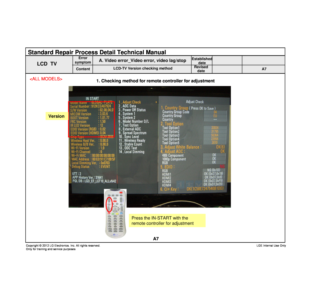
A. Video errorVideo error, video lag/stop
When the signal is strong, use the attenuator -10dB, -15dB, -20dB etc
Standard Repair Process Detail Technical Manual
Press the IN-START with the remote controller for adjustment
1. Checking method for remote controller for adjustment
ALL MODELS
Version
You can view 6 types of patterns using the ADJ Key
A. Video errorColor error
Appendix Exchange T-Con Board
Appendix Exchange T-Con Board
No Light
Appendix Exchange PSULED driver
Dim Light
No picture/Sound Ok A - 3/5
Un-repairable Cases In this case please exchange the module
Appendix Exchange the Module
Panel Mura, Light leakage
Press damage
Un-repairable Cases In this case please exchange the module
2. Check the entry into adjustment item
1. Press the IN-START button of the remote controller for adjustment
B. Power error Off when on, off whiling viewing
Entry method
1. Press the MENU button on the remote controller
C. Audio errorNo audio/Normal video
Checking method
2. Select the AUDIO function of the Menu