Location and function of controls
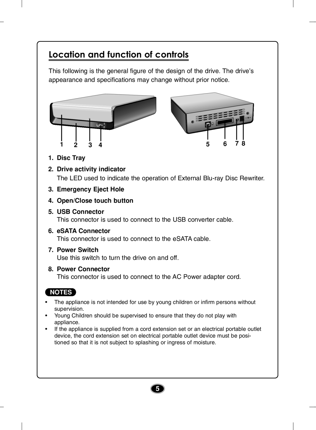
This following is the general figure of the design of the drive. The drive’s appearance and specifications may change without prior notice.
|
|
|
|
|
|
|
|
|
|
|
|
|
|
|
|
|
|
|
|
|
|
|
|
|
|
|
|
|
|
|
|
|
|
|
|
|
|
|
|
|
|
|
|
|
1 | 2 | 3 | 4 | 5 | 6 | 7 8 | ||||||||
|
|
|
|
|
|
|
|
|
|
|
|
|
|
|
1.Disc Tray
2.Drive activity indicator
The LED used to indicate the operation of External
3.Emergency Eject Hole
4.Open/Close touch button
5.USB Connector
This connector is used to connect to the USB converter cable.
6.eSATA Connector
This connector is used to connect to the eSATA cable.
7.Power Switch
Use this switch to turn the drive on and off.
8.Power Connector
This connector is used to connect to the AC Power adapter cord.
NOTES
•The appliance is not intended for use by young children or infirm persons without supervision.
•Young Children should be supervised to ensure that they do not play with appliance.
•If the appliance is supplied from a cord extension set or an electrical portable outlet device, the cord extension set on electrical portable outlet device must be posi- tioned so that it is not subject to splashing or ingress of moisture.
5
