EXTERNAL CONTROL DEVICE SETUP 27
EXTERNAL CONTROL DEVICE SETUP
ENGLISH
RS-232C Setup
Connect the
Connect the serial port of the control device to the
Note:
(CONTROL & SERVICE)
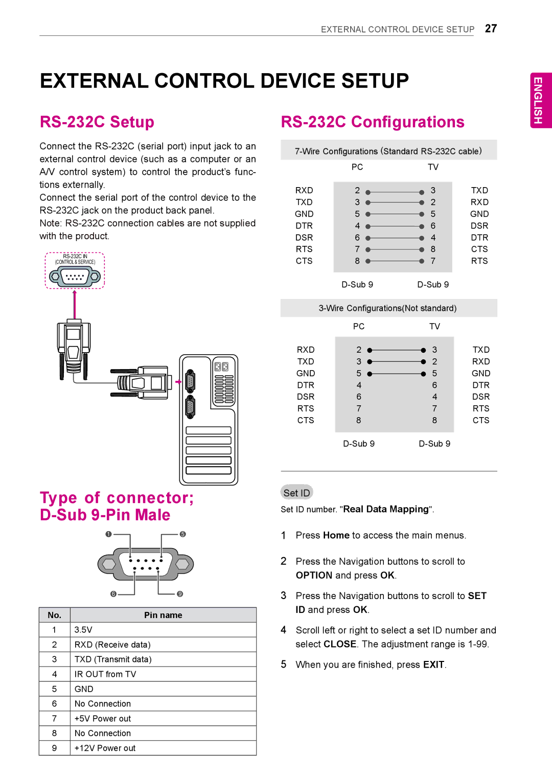
RS-232C Configurations
PCTV
RXD | 2 | 3 | TXD |
TXD | 3 | 2 | RXD |
GND | 5 | 5 | GND |
DTR | 4 | 6 | DSR |
DSR | 6 | 4 | DTR |
RTS | 7 | 8 | CTS |
CTS | 8 | 7 | RTS |
|
| ||
|
| ||
| PC | TV |
|
RXD | 2 | 3 | TXD |
TXD | 3 | 2 | RXD |
GND | 5 | 5 | GND |
DTR | 4 | 6 | DTR |
DSR | 6 | 4 | DSR |
RTS | 7 | 7 | RTS |
CTS | 8 | 8 | CTS |
|
| ||
Type of connector;
D-Sub 9-Pin Male
1 |
|
|
| 5 |
|
|
|
|
|
6 |
|
|
| 9 |
|
|
| ||
|
|
|
|
|
No. |
| Pin name | ||
13.5V
2RXD (Receive data)
3TXD (Transmit data)
4IR OUT from TV
5GND
6No Connection
7+5V Power out
8No Connection
9+12V Power out
Set ID
Set ID number. "Real Data Mapping".
1Press Home to access the main menus.
2Press the Navigation buttons to scroll to option and press ok.
3Press the Navigation buttons to scroll to set id and press ok.
4Scroll left or right to select a set ID number and select close. The adjustment range is
5When you are finished, press exit.