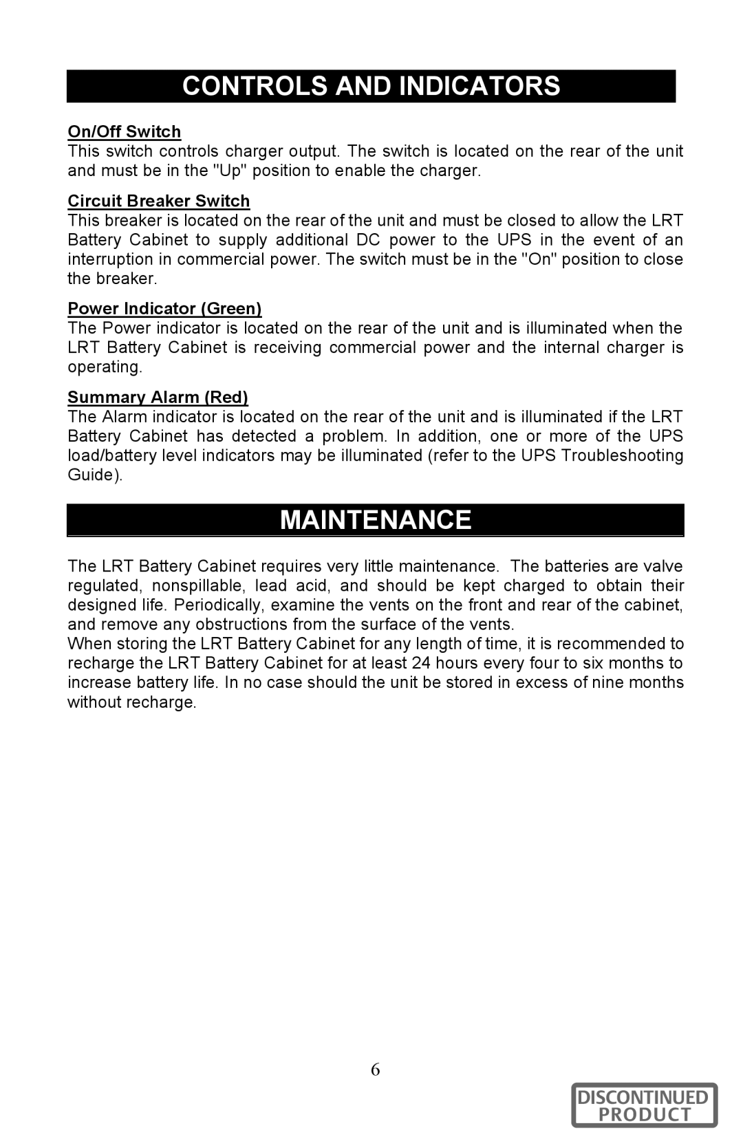
GXT96VLRT2UL specifications
The Liebert GXT96VLRT2UL is a high-performance uninterruptible power supply (UPS) designed to provide reliable backup power and enhanced protection for critical electronic equipment. With its advanced features and robust design, it caters to the needs of various applications, including data centers, telecom systems, and industrial environments.One of the standout features of the GXT96VLRT2UL is its double-conversion topology. This technology ensures that the equipment connected to the UPS receives a constant flow of clean and reliable power by converting incoming AC to DC and then back to AC again. This process effectively eliminates voltage fluctuations, surges, and electrical noise, ensuring that sensitive equipment operates optimally without interruption.
The GXT96VLRT2UL boasts a high input power factor, supporting energy efficiency and reducing the overall electrical demand. This is particularly crucial for organizations looking to minimize their power consumption and operational costs. Additionally, it has an output power rating of 10 kVA, making it suitable for handling substantial loads efficiently.
Another important characteristic is its flexible design. The Liebert GXT96VLRT2UL can be configured in both tower and rackmount modes, allowing it to adapt to different server room designs and space constraints. This versatility enables users to maximize available space while ensuring effective power management.
Furthermore, this UPS features a comprehensive digital display that provides real-time monitoring of power conditions and battery status. This user-friendly interface allows operators to easily access vital information regarding the UPS’s performance, making it easier to manage and maintain the system.
The Liebert GXT96VLRT2UL is equipped with Intelligent Battery Management technology, which extends battery life and optimizes recharge times. This feature helps reduce maintenance costs and ensures that the UPS is always ready to respond to power disruptions.
Additional enhancements include customizable alarms and notifications that keep users informed of any potential issues. Remote monitoring capabilities also allow for proactive management, increasing the reliability of the power protection strategy.
With its combination of advanced features, robust performance, and flexibility, the Liebert GXT96VLRT2UL stands out as a reliable choice for businesses seeking to protect their critical infrastructure from power disturbances. Its ability to ensure continuous operation during outages makes it an essential component in maintaining business continuity.