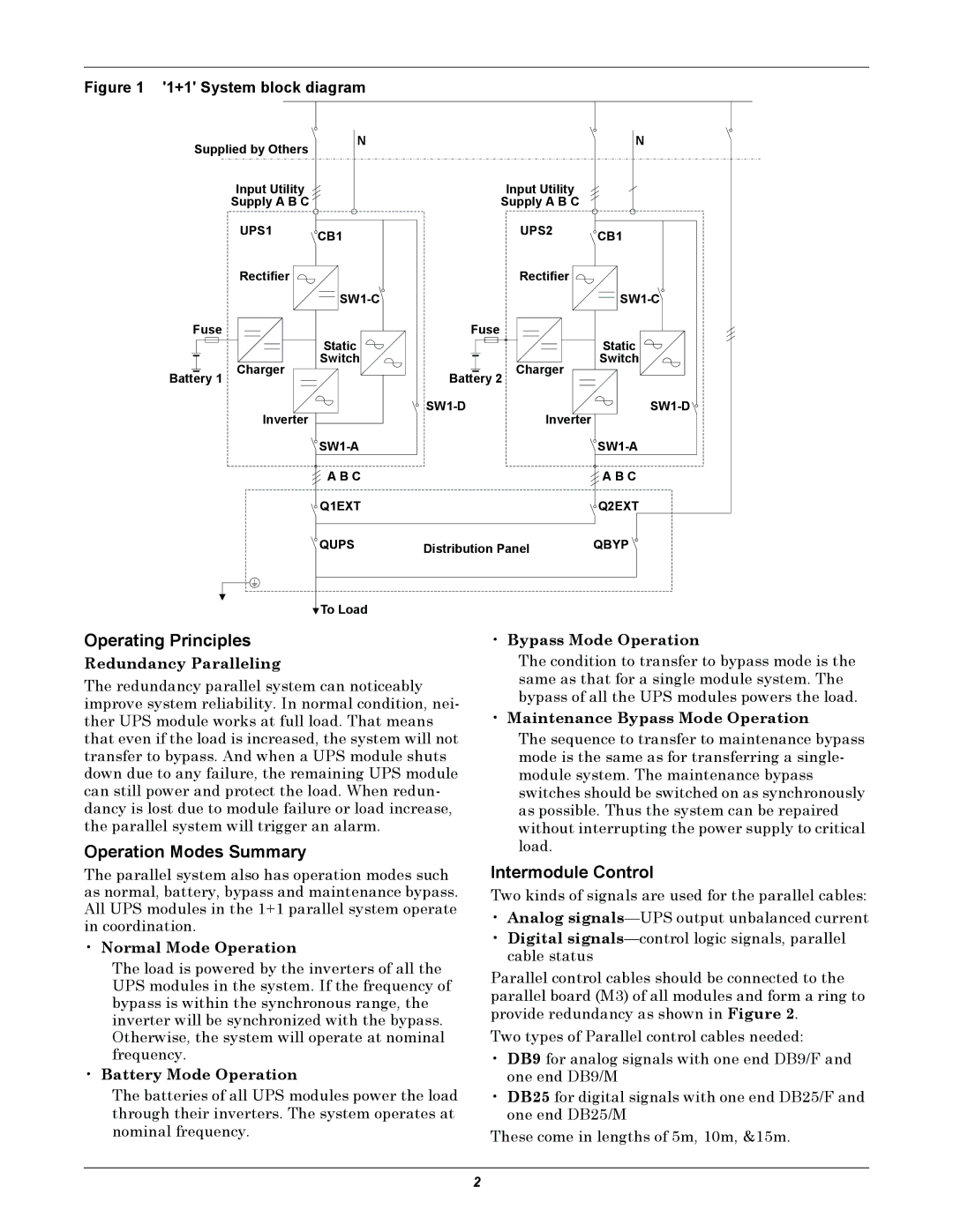
Figure 1 '1+1' System block diagram
Supplied by Others | N |
| N |
|
|
| |
Input Utility |
| Input Utility |
|
Supply A B C |
| Supply A B C |
|
UPS1 | CB1 | UPS2 | CB1 |
|
| ||
Rectifier |
| Rectifier |
|
|
| ||
Fuse | Static | Fuse | Static |
|
| ||
Battery 1 Charger | Switch | Battery 2 Charger | Switch |
|
| ||
Inverter |
| ||
| Inverter |
| |
|
| ||
| A B C |
| A B C |
| Q1EXT |
| Q2EXT |
| QUPS | Distribution Panel | QBYP |
![]() To Load
To Load
Operating Principles
Redundancy Paralleling
The redundancy parallel system can noticeably improve system reliability. In normal condition, nei- ther UPS module works at full load. That means that even if the load is increased, the system will not transfer to bypass. And when a UPS module shuts down due to any failure, the remaining UPS module can still power and protect the load. When redun- dancy is lost due to module failure or load increase, the parallel system will trigger an alarm.
Operation Modes Summary
The parallel system also has operation modes such as normal, battery, bypass and maintenance bypass. All UPS modules in the 1+1 parallel system operate in coordination.
•Normal Mode Operation
The load is powered by the inverters of all the UPS modules in the system. If the frequency of bypass is within the synchronous range, the inverter will be synchronized with the bypass. Otherwise, the system will operate at nominal frequency.
•Battery Mode Operation
The batteries of all UPS modules power the load through their inverters. The system operates at nominal frequency.
•Bypass Mode Operation
The condition to transfer to bypass mode is the same as that for a single module system. The bypass of all the UPS modules powers the load.
•Maintenance Bypass Mode Operation
The sequence to transfer to maintenance bypass mode is the same as for transferring a single- module system. The maintenance bypass switches should be switched on as synchronously as possible. Thus the system can be repaired without interrupting the power supply to critical load.
Intermodule Control
Two kinds of signals are used for the parallel cables:
•Analog
•Digital
Parallel control cables should be connected to the parallel board (M3) of all modules and form a ring to provide redundancy as shown in Figure 2.
Two types of Parallel control cables needed:
•DB9 for analog signals with one end DB9/F and one end DB9/M
•DB25 for digital signals with one end DB25/F and one end DB25/M
These come in lengths of 5m, 10m, &15m.
2