Liebherr 7085592-01 manual At the top, use a screwdriver to unclip cover 7

Models: 7085592-01

1 12
Download 12 pages 13.17 Kb
Page 6
Image 6
Fig. 8

Putting into operation

CAUTION


Risk of injury if the door tips!


u Take good hold of the door.


u Set down the door carefully.


u Unscrew the securing screw on


the bottom right turn hinge.


u Open the door.


u Hold the door on the handle side


and at the bottom and lift it.


w The bearing pin Fig. 4 (21) should


come out of the turn

hinge


Fig. 5 (2).


u If the bearing bolt Fig. 4 (21)


doesn't undo press it out

from

Fig. 4

underneath.


u Swing door out at the bottom and remove it.


Fig. 5

u Unscrew the turn hinge Fig. 5 (2).

u Unscrew the bearing element, Fig. 5 (3) transfer it to the opposite location hole of the turn hinge and screw it firmly into place.

u Take the stopper Fig. 5 (4) out of the turn hinge and transfer it to the receiving hole on the opposite side of the turn hinge.

u Carefully lift off the cover Fig. 5 (5) on the handle side.

u Undo the screw Fig. 5 (6) and transfer it to the opposite side. u Put the cover Fig. 5 (5) back on.

u Screw the turn hinge Fig. 5 (2) firmly into place on the new hinge side (with 4 Nm), possibly using a power screwdriver.

Fig. 6 u At the top, use a screwdriver to unclip cover Fig. 6 (7) and

cover Fig. 6 (8) at the front, and remove by pulling out and down.

u Unscrew the bearing pin Fig. 6 (9) and screw it firmly into place on the opposite side (with 4 Nm).

u Refit the cover Fig. 6 (7) on the side of the bearing pin: insert at the back, snap in at the front.

u Fit the cover Fig. 6 (8) on the opposite side: insert at the back, snap in at the front.

Fig. 7 u Lift the stopper Fig. 7 (12) out of the door bearing bush and

transfer it.

u Detach door handle, stoppers Fig. 7 (10) and pressure plates Fig. 7 (11) and transfer to the opposite side.

u When mounting the pressure plates, make sure they snap into place properly.

u Transfer the spring clamp Fig. 8 (20): Depress the latch nose and pull the spring clamp off over it.

u Slide the spring clamp into place on the new hinge side until it clicks into place.

u Pull the bearing pin Fig. 8 (21) out of the door bush and transfer it to the opposite side together with the washer. The latch nose must point to the inner side of the door, the notch to the outer side.

u Hang the door on the bearing pin Fig. 6 (9) at the top.

u Swing the door in at the bottom and insert the bearing pin Fig. 8 (21) into the turn hinge. If necessary, turn the bearing pin until it snaps into place.

u Insert the securing screw Fig. 4 (1) at the bottom into the bearing pin and tighten it (with 4 Nm).

u If necessary, align the door flush with the appliance housing using the two slots in the turn hinge. To do so, unscrew the middle screw.

WARNING

Risk of injury due to the door dropping out!

If the bearing parts are not screwed into place firmly enough, the door may drop out. This may lead to severe injuries. What is more, the door may not close and therefore the appliance may fail to cool properly.

u Screw on the bearing brackets/bearing pins tightly (4 Nm). u Check all of the screws and retighten if necessary.

6

* Depending on model and options

Page 6
Image 6
Liebherr 7085592-01 manual At the top, use a screwdriver to unclip cover 7

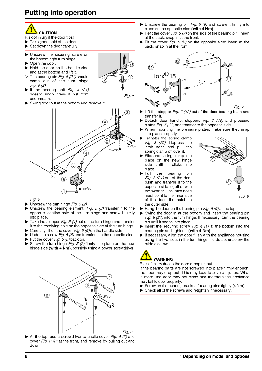
7085592-01 specifications

The Liebherr 7085592-01 is a cutting-edge component that exemplifies the advanced engineering and innovative technologies characteristic of Liebherr's product line. This particular part serves a critical role in the operation of Liebherr machinery, enhancing efficiency and reliability in a variety of applications.

One of the main features of the Liebherr 7085592-01 is its robust construction, designed to withstand the demanding environments typical in construction, mining, and industrial applications. The component is manufactured from high-quality materials that ensure optimum durability and longevity. This resiliency minimizes downtime, allowing for seamless operations, which is crucial for maximizing productivity on job sites.

In terms of technology, the Liebherr 7085592-01 incorporates advanced engineering principles that ensure precision and reliability. The component is designed with modern manufacturing techniques that guarantee a high degree of accuracy, which is essential for maintaining the performance standards expected from Liebherr products. This precision is further complemented by compatibility with a range of heavy equipment models, making it a versatile choice for various operational needs.

Another significant characteristic of the Liebherr 7085592-01 is its ease of installation and maintenance. The design facilitates straightforward assembly, enabling operators and technicians to replace or install the component quickly, thus reducing overall downtime. The user-friendly design is a testament to Liebherr’s commitment to not only enhancing performance but also ensuring that their products are accessible for maintenance and service.

Additionally, the 7085592-01 benefits from Liebherr’s comprehensive approach to quality assurance. Each component undergoes rigorous testing and inspection, ensuring it meets the high standards synonymous with the Liebherr brand. This attention to detail ensures that customers receive a product that not only performs exceptionally well but also adheres to safety regulations and operational guidelines.

In conclusion, the Liebherr 7085592-01 is more than just a component; it represents Liebherr’s dedication to innovation, durability, and customer satisfaction. Its robust design, technological sophistication, and ease of use make it an indispensable part of Liebherr’s machinery, affirming the company’s position as a leader in the heavy equipment industry. Whether it’s used in construction, mining, or any other heavy-duty application, this component stands ready to deliver optimal performance, ensuring that users can rely on Liebherr equipment to get the job done efficiently and effectively.