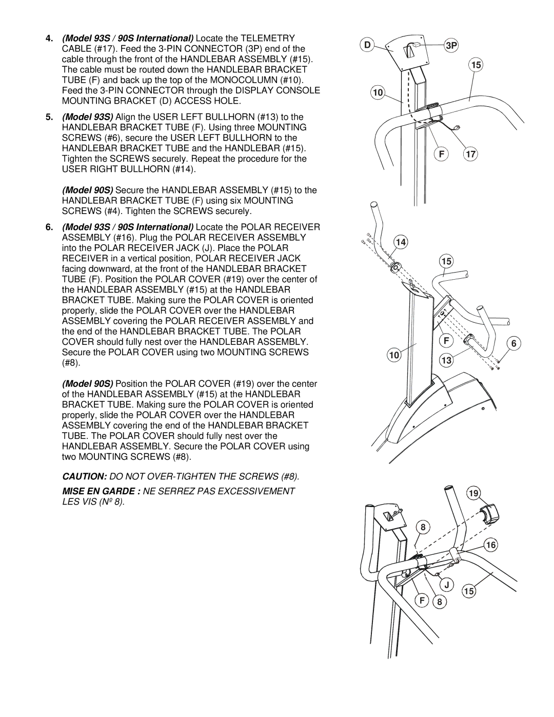
4.(Model 93S / 90S International) Locate the TELEMETRY CABLE (#17). Feed the
5.(Model 93S) Align the USER LEFT BULLHORN (#13) to the HANDLEBAR BRACKET TUBE (F). Using three MOUNTING SCREWS (#6), secure the USER LEFT BULLHORN to the HANDLEBAR BRACKET TUBE and the HANDLEBAR (#15). Tighten the SCREWS securely. Repeat the procedure for the USER RIGHT BULLHORN (#14).
(Model 90S) Secure the HANDLEBAR ASSEMBLY (#15) to the HANDLEBAR BRACKET TUBE (F) using six MOUNTING SCREWS (#4). Tighten the SCREWS securely.
6.(Model 93S / 90S International) Locate the POLAR RECEIVER ASSEMBLY (#16). Plug the POLAR RECEIVER ASSEMBLY into the POLAR RECEIVER JACK (J). Place the POLAR RECEIVER in a vertical position, POLAR RECEIVER JACK facing downward, at the front of the HANDLEBAR BRACKET TUBE (F). Position the POLAR COVER (#19) over the center of the HANDLEBAR ASSEMBLY (#15) at the HANDLEBAR BRACKET TUBE. Making sure the POLAR COVER is oriented properly, slide the POLAR COVER over the HANDLEBAR ASSEMBLY covering the POLAR RECEIVER ASSEMBLY and the end of the HANDLEBAR BRACKET TUBE. The POLAR COVER should fully nest over the HANDLEBAR ASSEMBLY. Secure the POLAR COVER using two MOUNTING SCREWS (#8).
(Model 90S) Position the POLAR COVER (#19) over the center of the HANDLEBAR ASSEMBLY (#15) at the HANDLEBAR BRACKET TUBE. Making sure the POLAR COVER is oriented properly, slide the POLAR COVER over the HANDLEBAR ASSEMBLY covering the end of the HANDLEBAR BRACKET TUBE. The POLAR COVER should fully nest over the HANDLEBAR ASSEMBLY. Secure the POLAR COVER using two MOUNTING SCREWS (#8).
CAUTION: DO NOT
MISE EN GARDE : NE SERREZ PAS EXCESSIVEMENT LES VIS (Nº 8).
D | 3P |
10
F
14
15
F
10 13
8
J
F 8
15
17
6
19
16
15