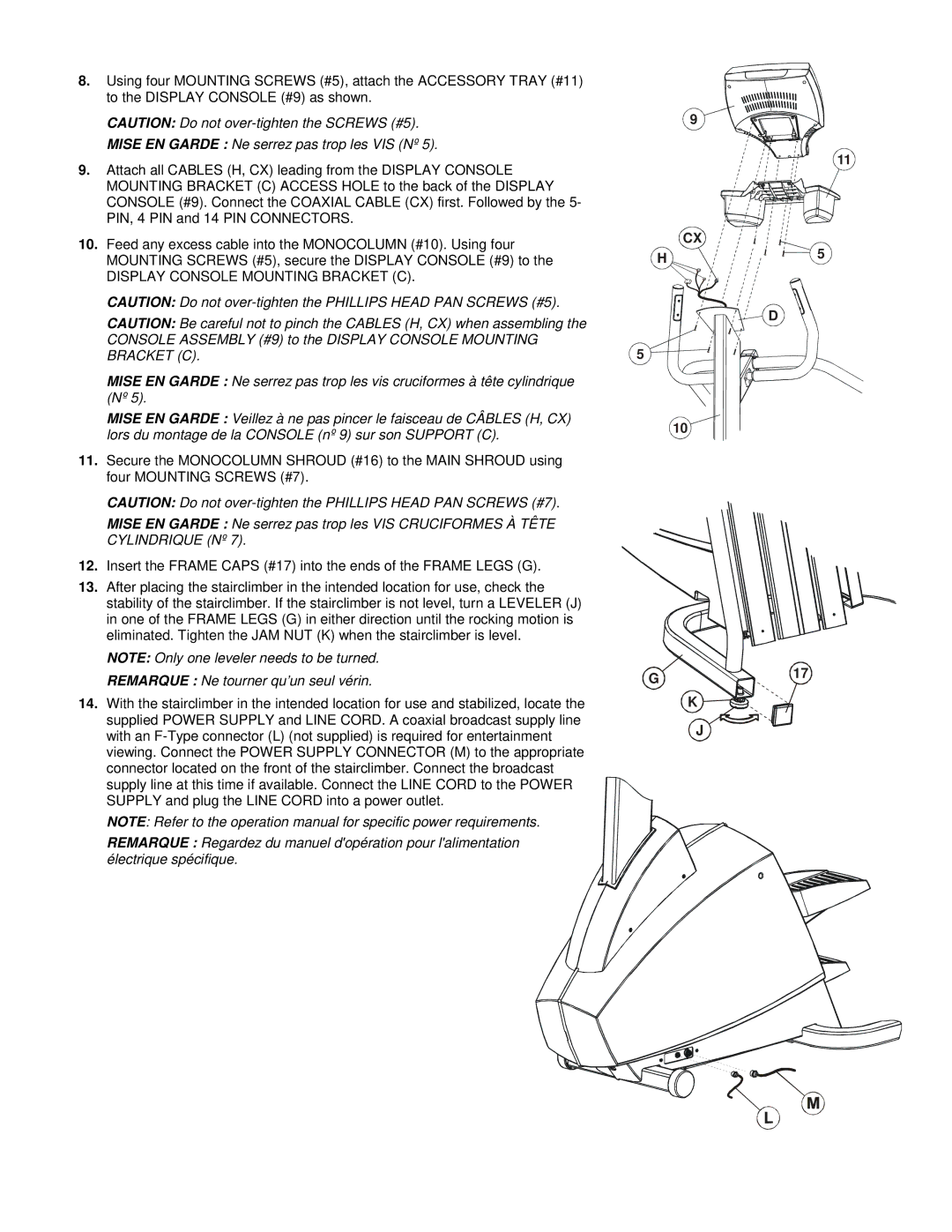
8.Using four MOUNTING SCREWS (#5), attach the ACCESSORY TRAY (#11) to the DISPLAY CONSOLE (#9) as shown.
CAUTION: Do not
MISE EN GARDE : Ne serrez pas trop les VIS (Nº 5).
9.Attach all CABLES (H, CX) leading from the DISPLAY CONSOLE MOUNTING BRACKET (C) ACCESS HOLE to the back of the DISPLAY CONSOLE (#9). Connect the COAXIAL CABLE (CX) first. Followed by the 5- PIN, 4 PIN and 14 PIN CONNECTORS.
10.Feed any excess cable into the MONOCOLUMN (#10). Using four MOUNTING SCREWS (#5), secure the DISPLAY CONSOLE (#9) to the
DISPLAY CONSOLE MOUNTING BRACKET (C).
CAUTION: Do not
CAUTION: Be careful not to pinch the CABLES (H, CX) when assembling the CONSOLE ASSEMBLY (#9) to the DISPLAY CONSOLE MOUNTING BRACKET (C).
MISE EN GARDE : Ne serrez pas trop les vis cruciformes à tête cylindrique (Nº 5).
MISE EN GARDE : Veillez à ne pas pincer le faisceau de CÂBLES (H, CX) lors du montage de la CONSOLE (nº 9) sur son SUPPORT (C).
11.Secure the MONOCOLUMN SHROUD (#16) to the MAIN SHROUD using four MOUNTING SCREWS (#7).
CAUTION: Do not
MISE EN GARDE : Ne serrez pas trop les VIS CRUCIFORMES À TÊTE CYLINDRIQUE (Nº 7).
12.Insert the FRAME CAPS (#17) into the ends of the FRAME LEGS (G).
13.After placing the stairclimber in the intended location for use, check the stability of the stairclimber. If the stairclimber is not level, turn a LEVELER (J) in one of the FRAME LEGS (G) in either direction until the rocking motion is eliminated. Tighten the JAM NUT (K) when the stairclimber is level.
NOTE: Only one leveler needs to be turned.
REMARQUE : Ne tourner qu’un seul vérin.
14.With the stairclimber in the intended location for use and stabilized, locate the supplied POWER SUPPLY and LINE CORD. A coaxial broadcast supply line with an
NOTE: Refer to the operation manual for specific power requirements.
REMARQUE : Regardez du manuel d'opération pour l'alimentation électrique spécifique.
9
CX
H
5
10
G
K
J
11
5
D
17
