3.7ACCESSORY TRAYS & CONSOLE
Parts: Hardware Bag #5 | (2, 8mm Phillips Screws) |
| (4, 12mm |
Tools: Phillips Screwdriver |
|
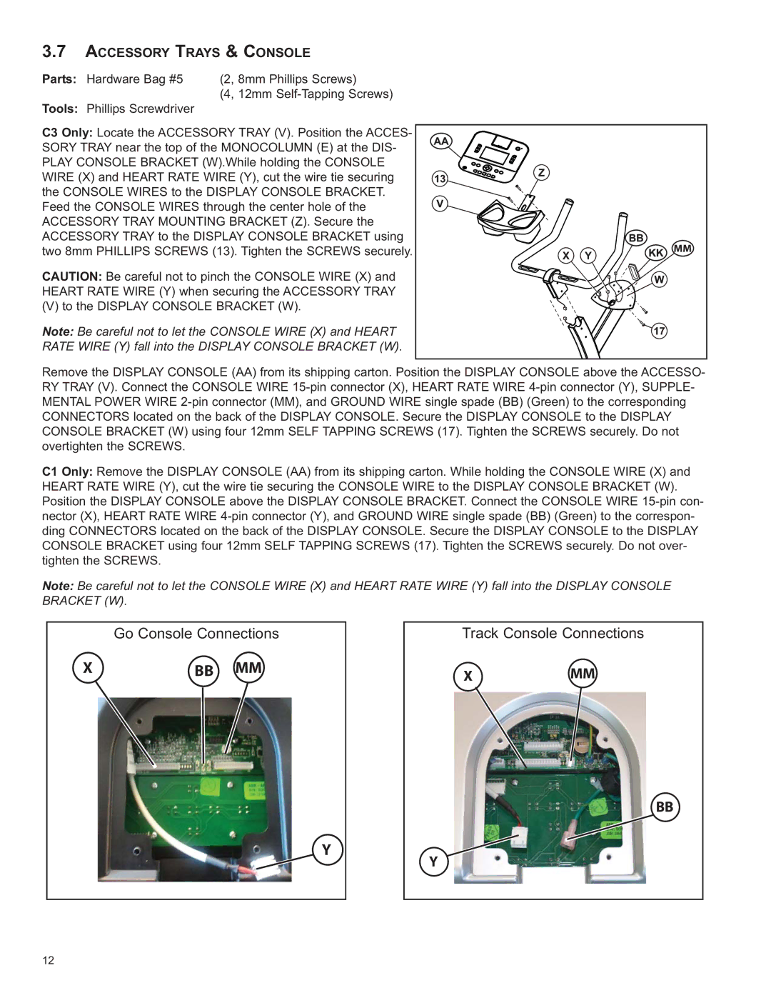
C3 Only: Locate the ACCESSORY TRAY (V). Position the ACCES- SORY TRAY near the top of the MONOCOLUMN (E) at the DIS- PLAY CONSOLE BRACKET (W).While holding the CONSOLE WIRE (X) and HEART RATE WIRE (Y), cut the wire tie securing the CONSOLE WIRES to the DISPLAY CONSOLE BRACKET. Feed the CONSOLE WIRES through the center hole of the ACCESSORY TRAY MOUNTING BRACKET (Z). Secure the ACCESSORY TRAY to the DISPLAY CONSOLE BRACKET using two 8mm PHILLIPS SCREWS (13). Tighten the SCREWS securely.
CAUTION: Be careful not to pinch the CONSOLE WIRE (X) and HEART RATE WIRE (Y) when securing the ACCESSORY TRAY
(V) to the DISPLAY CONSOLE BRACKET (W).
Note: Be careful not to let the CONSOLE WIRE (X) and HEART RATE WIRE (Y) fall into the DISPLAY CONSOLE BRACKET (W).
MM |
Remove the DISPLAY CONSOLE (AA) from its shipping carton. Position the DISPLAY CONSOLE above the ACCESSO- RY TRAY (V). Connect the CONSOLE WIRE
C1 Only: Remove the DISPLAY CONSOLE (AA) from its shipping carton. While holding the CONSOLE WIRE (X) and HEART RATE WIRE (Y), cut the wire tie securing the CONSOLE WIRE to the DISPLAY CONSOLE BRACKET (W). Position the DISPLAY CONSOLE above the DISPLAY CONSOLE BRACKET. Connect the CONSOLE WIRE
Note: Be careful not to let the CONSOLE WIRE (X) and HEART RATE WIRE (Y) fall into the DISPLAY CONSOLE BRACKET (W).
Go Console Connections
X | BB MM |
Y
Track Console Connections
XMM
BB
Y
12