40
2
39
4
3
1
A
44 43
43 42
6
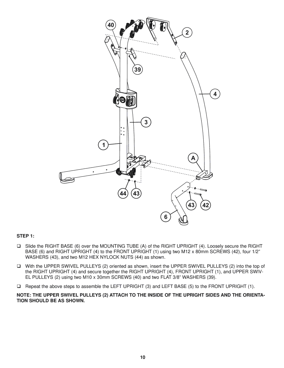
STEP 1:
Slide the RIGHT BASE (6) over the MOUNTING TUBE (A) of the RIGHT UPRIGHT (4). Loosely secure the RIGHT BASE (6) and RIGHT UPRIGHT (4) to the FRONT UPRIGHT (1) using two M12 x 80mm SCREWS (42), four 1/2” WASHERS (43), and two M12 HEX NYLOCK NUTS (44) as shown.
With the UPPER SWIVEL PULLEYS (2) oriented as shown, insert the UPPER SWIVEL PULLEYS (2) into the top of the RIGHT UPRIGHT (4) and secure together the RIGHT UPRIGHT (4), FRONT UPRIGHT (1), and UPPER SWIV- EL PULLEYS (2) using two M10 x 30mm SCREWS (40) and two FLAT 3/8” WASHERS (39).
Repeat the above steps to assemble the LEFT UPRIGHT (3) and LEFT BASE (5) to the FRONT UPRIGHT (1).
NOTE: THE UPPER SWIVEL PULLEYS (2) ATTACH TO THE INSIDE OF THE UPRIGHT SIDES AND THE ORIENTA- TION SHOULD BE AS SHOWN.
10