|
| 46 | |
1” | 45 | 10 | |
49 | |||
| |||
|
| ||
|
| 11 | |
| 46 | 45 | |
| 8 | 12 | |
|
| ||
|
| 9 |
1 | 8 |
| |
| 13 |
B
STEP 3:
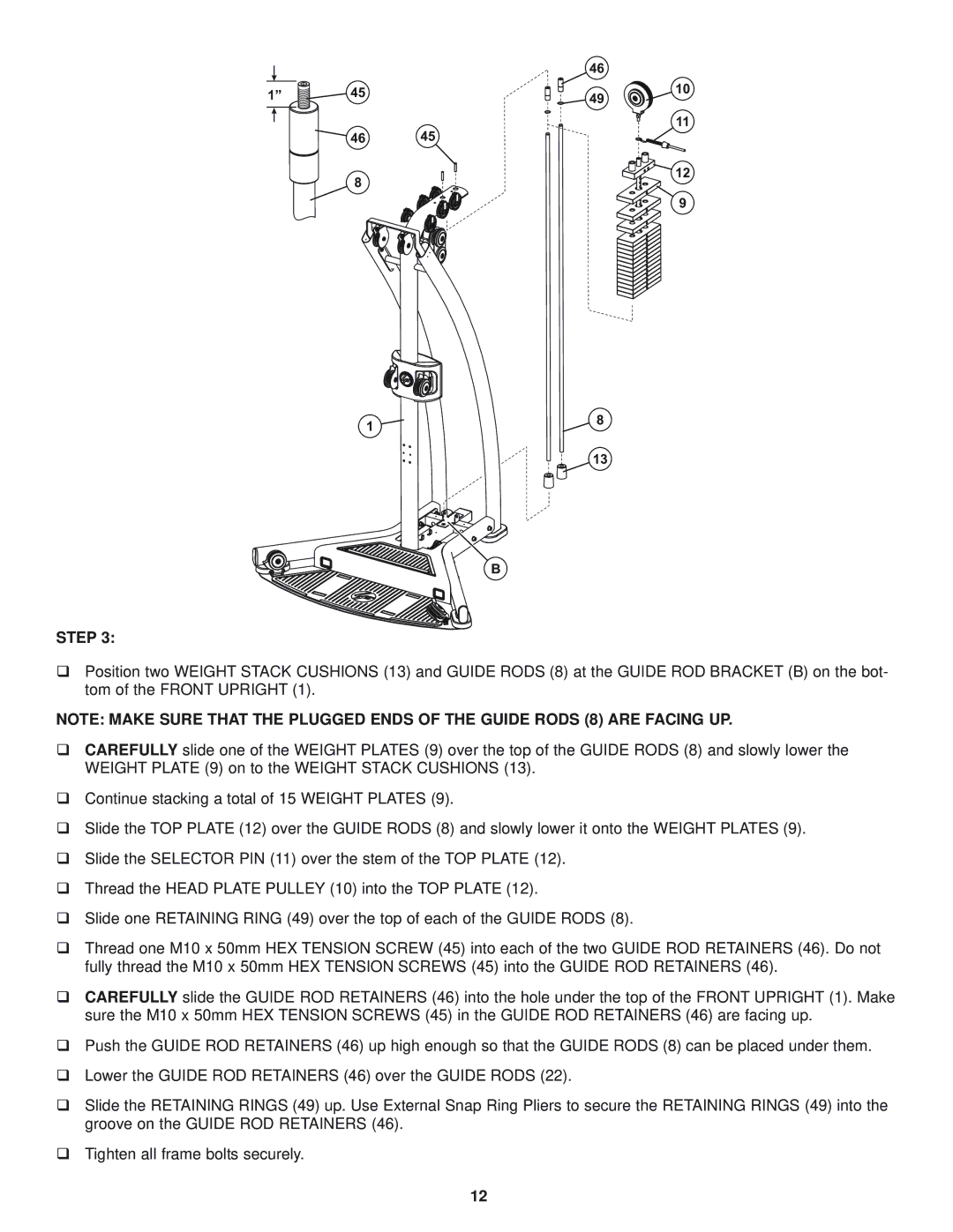
Position two WEIGHT STACK CUSHIONS (13) and GUIDE RODS (8) at the GUIDE ROD BRACKET (B) on the bot- tom of the FRONT UPRIGHT (1).
NOTE: MAKE SURE THAT THE PLUGGED ENDS OF THE GUIDE RODS (8) ARE FACING UP.
CAREFULLY slide one of the WEIGHT PLATES (9) over the top of the GUIDE RODS (8) and slowly lower the WEIGHT PLATE (9) on to the WEIGHT STACK CUSHIONS (13).
Continue stacking a total of 15 WEIGHT PLATES (9).
Slide the TOP PLATE (12) over the GUIDE RODS (8) and slowly lower it onto the WEIGHT PLATES (9).
Slide the SELECTOR PIN (11) over the stem of the TOP PLATE (12).
Thread the HEAD PLATE PULLEY (10) into the TOP PLATE (12).
Slide one RETAINING RING (49) over the top of each of the GUIDE RODS (8).
Thread one M10 x 50mm HEX TENSION SCREW (45) into each of the two GUIDE ROD RETAINERS (46). Do not fully thread the M10 x 50mm HEX TENSION SCREWS (45) into the GUIDE ROD RETAINERS (46).
CAREFULLY slide the GUIDE ROD RETAINERS (46) into the hole under the top of the FRONT UPRIGHT (1). Make sure the M10 x 50mm HEX TENSION SCREWS (45) in the GUIDE ROD RETAINERS (46) are facing up.
Push the GUIDE ROD RETAINERS (46) up high enough so that the GUIDE RODS (8) can be placed under them.
Lower the GUIDE ROD RETAINERS (46) over the GUIDE RODS (22).
Slide the RETAINING RINGS (49) up. Use External Snap Ring Pliers to secure the RETAINING RINGS (49) into the groove on the GUIDE ROD RETAINERS (46).
Tighten all frame bolts securely.
12