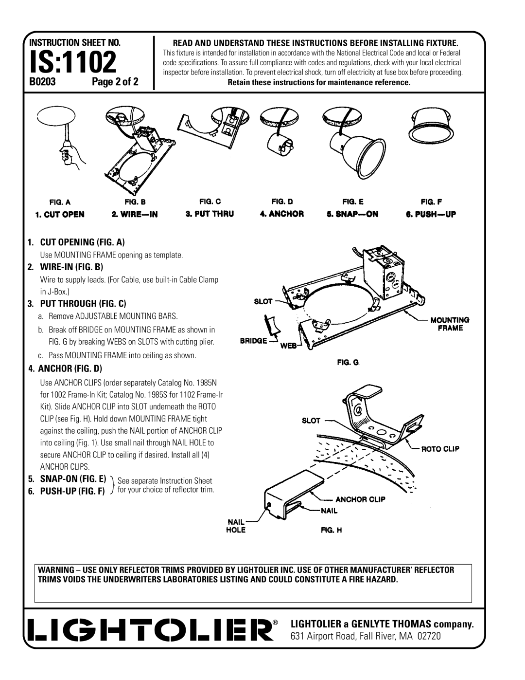
1002, 1102, 1202 specifications
Lightolier, a name synonymous with innovative lighting solutions, has carved a niche for itself in the lighting industry with its signature products such as the 1202, 1002, and 1102 series. These fixtures are designed to provide both functional illumination and aesthetic appeal, making them ideal for various applications, from residential to commercial spaces.The Lightolier 1202 model is celebrated for its versatility and efficiency. It is a recessed lighting fixture that employs advanced LED technology, delivering superior light output while consuming minimal energy. The fixture features an adjustable trim that allows users to direct light where it is most needed, making it perfect for task lighting or accentuating architectural elements. With a sleek design, the 1202 is compatible with multiple ceiling types and provides seamless integration into any space.
In contrast, the Lightolier 1002 series stands out for its minimalist design and adaptability. This model is particularly popular in modern interiors, offering a clean aesthetic without compromising on performance. The 1002 series is designed with a broad beam angle, ensuring uniform light distribution across spaces. Additionally, it supports dimming capabilities, enabling users to create the perfect ambiance for any occasion. The fixture’s durable construction ensures longevity, making it a valuable investment for any lighting project.
The Lightolier 1102 model showcases cutting-edge technology, featuring an integrated wireless control system that allows for smart lighting management. Users can easily adjust the brightness and color temperature through a mobile app or smart home devices, promoting energy efficiency and convenience. The 1102 series is particularly effective for commercial environments where different lighting scenarios are required throughout the day. Its sophisticated design allows for easy installation and maintenance, making it a favorite among professionals in the industry.
All three models—1202, 1002, and 1102—incorporate eco-friendly features, reflecting Lightolier's commitment to sustainability. They utilize energy-efficient LED technology, significantly reducing energy consumption compared to traditional lighting. The fixtures also have a long lifespan, contributing to lower replacement costs and less environmental waste.
In summary, the Lightolier 1202, 1002, and 1102 models are distinguished by their innovative features, advanced technologies, and versatile applications. Whether for residential or commercial use, these fixtures embody a perfect blend of style, functionality, and efficiency, catering to the diverse needs of modern lighting design.

