READ AND UNDERSTAND ALL TRACK, CONNECTOR, FEED-IN-KITS, AND ACCESSORY

INSTRUCTION SHEETS BEFORE INSTALLING ANY PROSPEC™ TRACK ITEM.

This fixture is intended for installation in accordance with the National Electrical Code and local or Federal code specifications. To assure full compliance with codes and regulations, check with your local electrical inspector before installation. To prevent electric shock, turn off electricity at fuse box before proceeding.

Retain these instructions for maintenance reference.

INSTRUCTION SHEET NO.

IS:26050

A0197

Page 1 of 2

Installation Instructions for ProSpec, In-Line, "L", "T", and "X" Connectors / Circuit Diagrams

For use with ProSpecTrack System Only.

Caution:

Turn off power at fuse box before installing track.

Instructions for grounding Feed-in Kit must be followed. Failure to do so may result in a hazardous condition.

Use only #12 ga. solid copper wire in connectors to maintain proper track rating.

Observe polarity, white (neutral) wire must be connected to terminal marked "NEUT". Failure to observe Polarity may result in an electrical hazard.

Do not use Track as a conduit support. Independent conduit supports (such as suitable conduit straps) must be used to attach the conduit installation to the building structure.

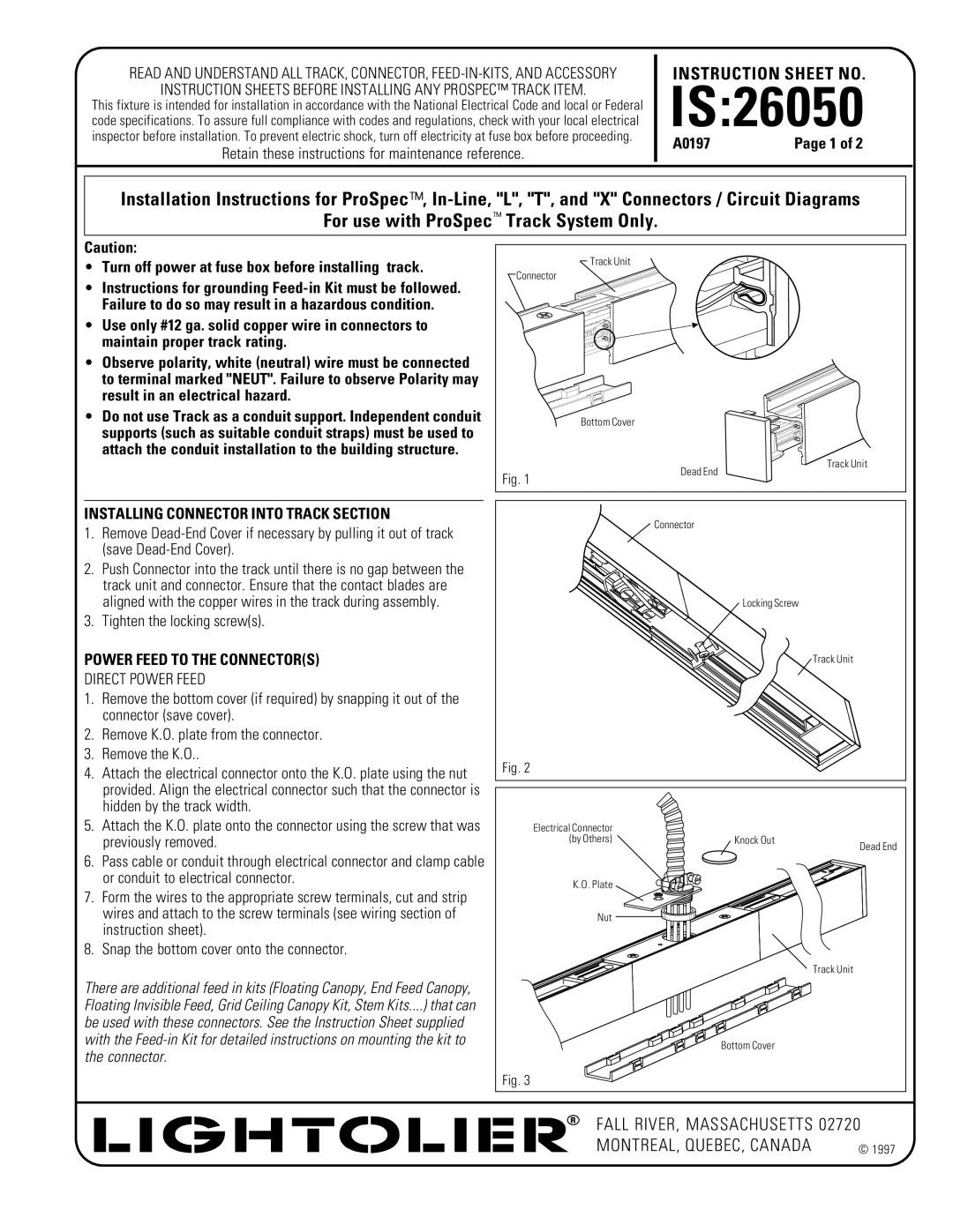
INSTALLING CONNECTOR INTO TRACK SECTION

1.Remove Dead-End Cover if necessary by pulling it out of track (save Dead-End Cover).

2.Push Connector into the track until there is no gap between the track unit and connector. Ensure that the contact blades are aligned with the copper wires in the track during assembly.

3.Tighten the locking screw(s).

POWER FEED TO THE CONNECTOR(S)

DIRECT POWER FEED

1.Remove the bottom cover (if required) by snapping it out of the connector (save cover).

2.Remove K.O. plate from the connector.

3.Remove the K.O..

4.Attach the electrical connector onto the K.O. plate using the nut provided. Align the electrical connector such that the connector is hidden by the track width.

5.Attach the K.O. plate onto the connector using the screw that was previously removed.

6.Pass cable or conduit through electrical connector and clamp cable or conduit to electrical connector.

7.Form the wires to the appropriate screw terminals, cut and strip wires and attach to the screw terminals (see wiring section of instruction sheet).

8.Snap the bottom cover onto the connector.

There are additional feed in kits (Floating Canopy, End Feed Canopy, Floating Invisible Feed, Grid Ceiling Canopy Kit, Stem Kits....) that can

be used with these connectors. See the Instruction Sheet supplied with the Feed-in Kit for detailed instructions on mounting the kit to the connector.


Track Unit

Connector


Bottom Cover


Track Unit

Fig. 1

Dead End


Connector

Locking Screw

Track Unit

Fig. 2

Electrical Connector


(by Others)

Knock Out

Dead End


K.O. Plate


Nut


Track Unit


Bottom Cover


Fig. 3


FALL RIVER, MASSACHUSETTS 02720

MONTREAL, QUEBEC, CANADA

© 1997

Page 1
Image 1
Lightolier instruction sheet IS26050, For use with ProSpec Track System Only, Installing Connector Into Track Section

26050 specifications

The Lightolier 26050 is a versatile and innovative lighting fixture designed to enhance both residential and commercial spaces. As part of the Lightolier brand, which is renowned for its commitment to quality and aesthetic appeal, the 26050 exemplifies modern lighting technology coupled with user-friendly functionality.

One of the defining features of the Lightolier 26050 is its energy-efficient design. The fixture utilizes LED technology, making it not only environmentally friendly but also cost-effective in the long run. LED lights can significantly reduce energy consumption compared to traditional incandescent bulbs, resulting in lower electricity bills and a smaller carbon footprint. Additionally, the longevity of LED lights means they require less frequent replacement, minimizing maintenance efforts.

The 26050 model is known for its sleek and contemporary design, making it suitable for various applications, ranging from residential living rooms to commercial offices. Its clean lines and minimalist aesthetic enable it to blend seamlessly with different interior styles. The fixture is available in a range of finishes, allowing customers to select options that best complement their decor.

Another notable characteristic of the Lightolier 26050 is its adjustable lighting capabilities. With features that allow for multiple brightness settings and color temperatures, users can create the desired ambiance for any occasion. This flexibility is particularly beneficial in spaces that serve multiple purposes, such as a multipurpose room that may need bright lighting for work and softer lighting for relaxation.

Installation of the Lightolier 26050 is straightforward, with options for both recessed and surface mounting, catering to diverse architectural requirements. Furthermore, the fixture is compatible with smart home systems, enabling users to control their lighting through mobile apps or voice-command technology. This integration adds an extra layer of convenience and modernity to the lighting experience.

In summary, the Lightolier 26050 is a highly functional and stylish lighting solution. Its energy-efficient LED technology, adjustable lighting options, and compatibility with smart home systems make it a standout choice for both residential and commercial use. With its aesthetic versatility and ease of installation, the Lightolier 26050 continues to set a high standard in the world of modern lighting fixtures.