READ AND UNDERSTAND ALL TRACK, CONNECTOR,
INSTRUCTION SHEETS BEFORE INSTALLING ANY TRACK ITEM.
This fixture is intended for installation in accordance with the National Electrical Code and local or Federal code specifications. To assure full compliance with codes and regulations, check with your local electrical inspector before installation. To prevent electric shock, turn off electricity at fuse box before proceeding.
Retain these instructions for maintenance reference.
INSTRUCTION SHEET NO.
IS:7480
B1197 | Page 1 of 2 |
Installation Instructions for Swivel Stem Mounting Kits for use with Lytespan and ProSpec™ Track Systems Only.
Caution:
• | Turn off power at fuse box before installing track. |
• Instructions for grounding must be followed. Failure to do | |
| so may result in a hazardous condition. |
• Use only #12 ga. solid copper wire in connectors to maintain | |
| proper track rating. |
• | Do not supply Advent Track from two separate 120V branch |
| circuits as this could overload the neutral track conductor |
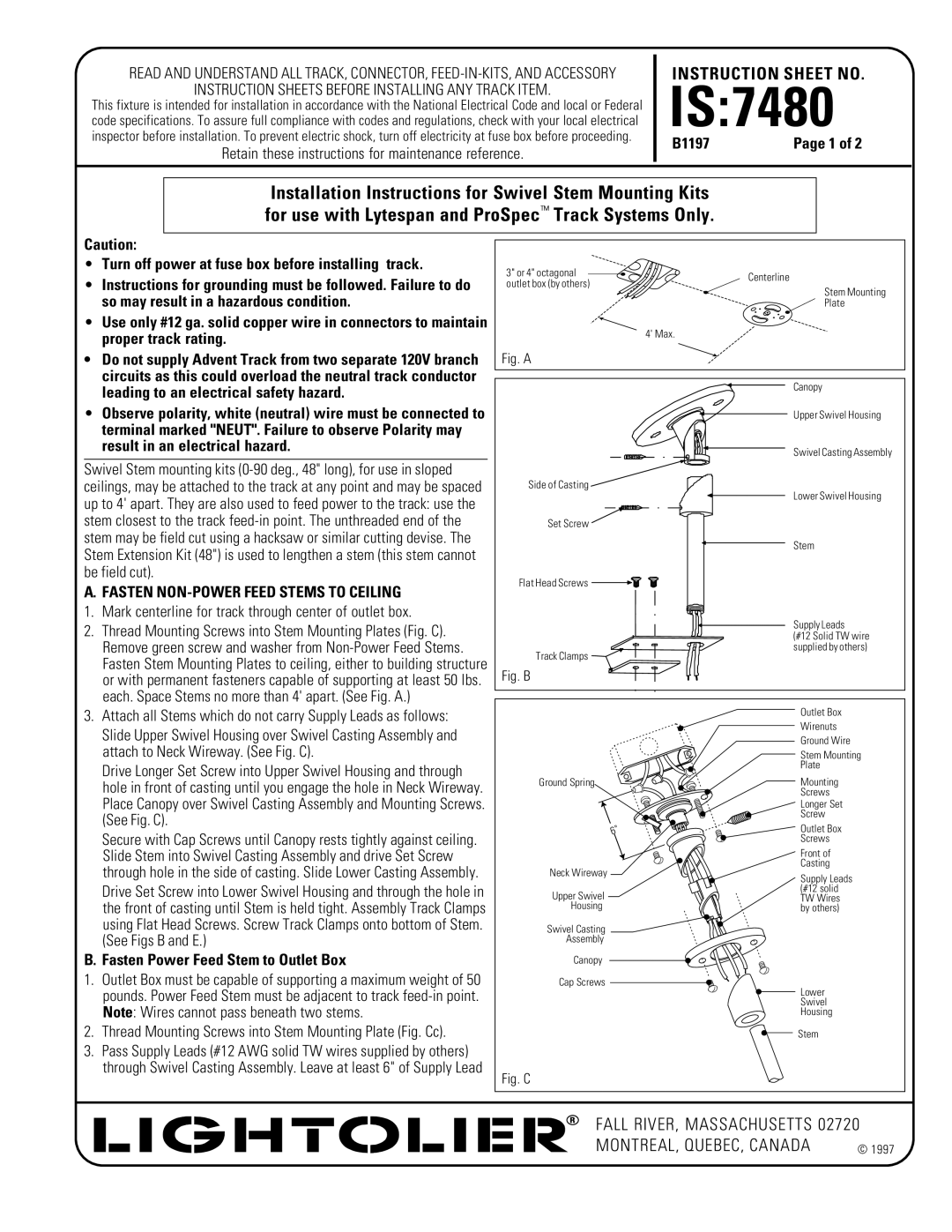
3" or 4" octagonal | Centerline | |
outlet box (by others) | ||
|
Stem Mounting
Plate
4' Max.
Fig. A
leading to an electrical safety hazard. |
• Observe polarity, white (neutral) wire must be connected to |
terminal marked "NEUT". Failure to observe Polarity may |
result in an electrical hazard. |
Swivel Stem mounting kits
A.FASTEN NON-POWER FEED STEMS TO CEILING
1. Mark centerline for track through center of outlet box.
2. Thread Mounting Screws into Stem Mounting Plates (Fig. C). |
Remove green screw and washer from |
Fasten Stem Mounting Plates to ceiling, either to building structure |
or with permanent fasteners capable of supporting at least 50 lbs. |
each. Space Stems no more than 4' apart. (See Fig. A.) |
Side of Casting
Set Screw
Flat Head Screws ![]()
![]()
Track Clamps
Fig. B
Canopy
Upper Swivel Housing
Swivel Casting Assembly
Lower Swivel Housing
Stem
Supply Leads
(#12 Solid TW wire supplied by others)
3. Attach all Stems which do not carry Supply Leads as follows: |
Slide Upper Swivel Housing over Swivel Casting Assembly and |
attach to Neck Wireway. (See Fig. C). |
Drive Longer Set Screw into Upper Swivel Housing and through |
hole in front of casting until you engage the hole in Neck Wireway. |
Place Canopy over Swivel Casting Assembly and Mounting Screws. |
(See Fig. C). |
Secure with Cap Screws until Canopy rests tightly against ceiling. |
Slide Stem into Swivel Casting Assembly and drive Set Screw |
through hole in the side of casting. Slide Lower Casting Assembly. |
Drive Set Screw into Lower Swivel Housing and through the hole in the front of casting until Stem is held tight. Assembly Track Clamps using Flat Head Screws. Screw Track Clamps onto bottom of Stem. (See Figs B and E.)
Ground Spring
Neck Wireway
Upper Swivel
Housing
Swivel Casting |
Assembly |
Outlet Box
Wirenuts
Ground Wire
Stem Mounting
Plate
Mounting
Screws
Longer Set
Screw
Outlet Box
Screws
Front of
Casting
Supply Leads (#12 solid TW Wires by others)
B. Fasten Power Feed Stem to Outlet Box
1.Outlet Box must be capable of supporting a maximum weight of 50 pounds. Power Feed Stem must be adjacent to track
2.Thread Mounting Screws into Stem Mounting Plate (Fig. Cc).
3.Pass Supply Leads (#12 AWG solid TW wires supplied by others) through Swivel Casting Assembly. Leave at least 6" of Supply Lead
Canopy
Cap Screws
Lower
Swivel
Housing
Stem
Fig. C
FALL RIVER, MASSACHUSETTS 02720
MONTREAL, QUEBEC, CANADA | © 1997 |