INSTRUCTION SHEET NO.
IS:7480
B1197 | Page 2 of 2 |
Installation Instructions for Stem Mounting Kit
for use with Lytespan and ProSpec™ Track Systems Only.
for splicing, and enough wire to run horizontally along upper section of track to power
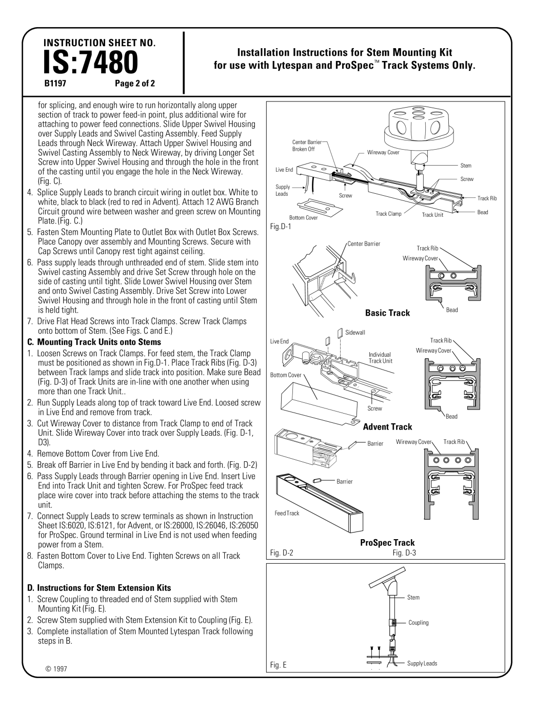
4.Splice Supply Leads to branch circuit wiring in outlet box. White to white, black to black (red to red in Advent). Attach 12 AWG Branch Circuit ground wire between washer and green screw on Mounting Plate. (Fig. C.)
5.Fasten Stem Mounting Plate to Outlet Box with Outlet Box Screws. Place Canopy over assembly and Mounting Screws. Secure with Cap Screws until Canopy rest tight against ceiling.
6.Pass supply leads through unthreaded end of stem. Slide stem into Swivel casting Assembly and drive Set Screw through hole on the side of casting until tight. Slide Lower Swivel Housing over Stem and onto Swivel Casting Assembly. Drive Set Screw into Lower Swivel Housing and through hole in the front of casting until Stem is held tight.
7.Drive Flat Head Screws into Track Clamps. Screw Track Clamps onto bottom of Stem. (See Figs. C and E.)
C. Mounting Track Units onto Stems
1.Loosen Screws on Track Clamps. For feed stem, the Track Clamp must be positioned as shown in
2.Run Supply Leads along top of track toward Live End. Loosed screw in Live End and remove from track.
3.Cut Wireway Cover to distance from Track Clamp to end of Track Unit. Slide Wireway Cover into track over Supply Leads. (Fig.
4.Remove Bottom Cover from Live End.
5.Break off Barrier in Live End by bending it back and forth. (Fig.
6.Pass Supply Leads through Barrier opening in Live End. Insert Live End into Track Unit and tighten Screw. For ProSpec feed track place wire cover into track before attaching the stems to the track unit.
7.Connect Supply Leads to screw terminals as shown in Instruction Sheet IS:6020, IS:6121, for Advent, or IS:26000, IS:26046, IS:26050 for ProSpec. Ground terminal in Live End is not used when feeding power from a Stem.
8.Fasten Bottom Cover to Live End. Tighten Screws on all Track Clamps.
D. Instructions for Stem Extension Kits
1.Screw Coupling to threaded end of Stem supplied with Stem Mounting Kit (Fig. E).
2.Screw Stem supplied with Stem Extension Kit to Coupling (Fig. E).
3.Complete installation of Stem Mounted Lytespan Track following steps in B.
© 1997
Center Barrier |
|
|
|
|
Broken Off | Wireway Cover |
|
| |
|
|
| ||
Live End |
|
|
| Stem |
|
|
|
| |
|
|
|
| Screw |
Supply |
|
|
|
|
Leads | Screw |
|
| Track Rib |
|
|
| ||
|
|
|
| |
Bottom Cover | Track Clamp | Track Unit | Bead | |
|
|
|
| |
|
|
|
|
|
| Center Barrier |
| Track Rib |
|
|
|
|
| |
|
| Wireway Cover |
| |
| Basic Track |
| Bead | |
|
|
| ||
| Sidewall |
|
|
|
Live End |
|
| Track Rib | |
| Individual |
| Wireway Cover | |
|
|
|
| |
| Track Unit |
|
|
|
Bottom Cover |
|
|
|
|
| Screw |
|
|
|
|
|
|
| Bead |
| Advent Track |
|
| |
| Barrier | Wireway Cover | Track Rib | |
| Barrier |
|
|
|
Feed Track |
|
|
|
|
| ProSpec Track |
|
| |
Fig. |
| Fig. |
|
|
|
| Stem |
| |
|
| Coupling |
| |
Fig. E | Supply Leads |