/ |
|
|
| INSTRUCTIONSHEETNO. | ||
|
|
|
| |||
INSTALLATION | PROCEDURE | FOR | LOW VOLTAGE | lS:1055LV | ||
REFLECTOR TRIM IN THE 1000LV | ||||||
|
| |||||
|
|
|
| 0s90 | Page 1 of 2 | |
READ AND UNDERSTAND THESE lNSTRU~lONS BEFORE INSTALLING FIXTURE.
This fixture is intended for installation in accordance with the National Electrical Code and local regulation. To assure full compliance with local codes and regulations, check with your local electrical inspector before installation. To prevent electrical shock, turn off electricity at fuse box before proceeding.
Retain these instructions for maintenance reference.
~~%~
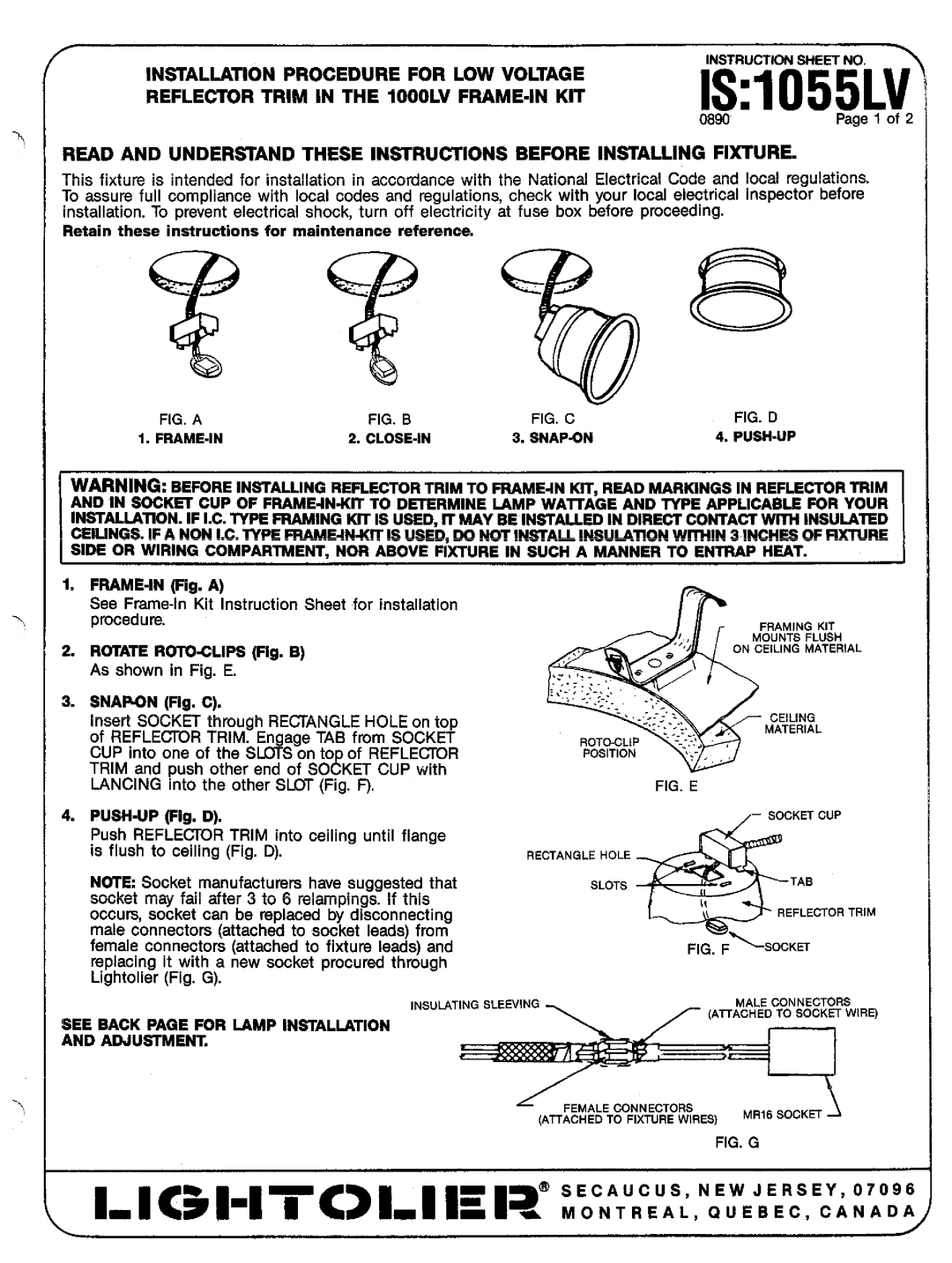
FIG. A | FIG. B | FIG. C | FIG. D |
1. | 2. | 3. SNAP~N | 4. |
WARNING: BEFORE INSTALLING REFLECTOR TRIM TO
1.
See
2.ROTATE
3.SNAP.ON (Fig. C).
Insert SOCKET through RECTANGLE HOLE on top of REFLECTOR TRIM. Engage TAB from SOCKET CUP into one of the SLOTS on top of REFLECTOR TRIM and push other end of SOCKET CUP with LANCING into the other SLOT (Fig. F),
4.
Push REFLECTOR TRIM into ceiling until flange is flueh to ceiling (Fig. D).
N~E Socket manufacturers have suggested that socket may fail after 3 to 6 ralampings. If this occurs, socket can be replaced by disconnecting male connectors (attached to socket leads) from female connectors (attached to fixture leads) and replacing it with a new socket procured through Lightolier (Fig. G).
r-
,..’ |
| ,!;; |
| |
| 0“ | \ | ||
|
| |||
;’,.’.’.; |
|
| ||
, | ....:.: | .’$.’. |
| |
|
| |||
|
|
| ||
ROTO.CLIP ‘““::;~y
POSITION :.,
4
FIG. E
RECTANGLEHOLE ~
SLOTa
FRAMINGKIT
MOUNTSFLUSH
ONCEILINGMATERIAL
CEILING
MATERIAL
;
,,
–SOCKETCUP
REFLECTORTRIM
INSULATINGSLEEVINGMALECONNECTORa
(ATTACHEDTO SOCKETWIRE)
SEE BACK PAGE FOR LAMP INSTALLATION
AND ADJU~MENT.
FEMALECONNECTORS
(ATTACHEDTO FIXTUREWIRES) MR16SOCKET
FIG. G
1- | I <51“17<> | 1= | ,a@ | :v:::::i,N:r::::,E:i:T:j |