INSTALLATION PROCEDURE FOR: LYTECASTER®
2000LV, 2000LVE1 & 2000LVE2 LOW VOLTAGE
KITS (CONTINUED)
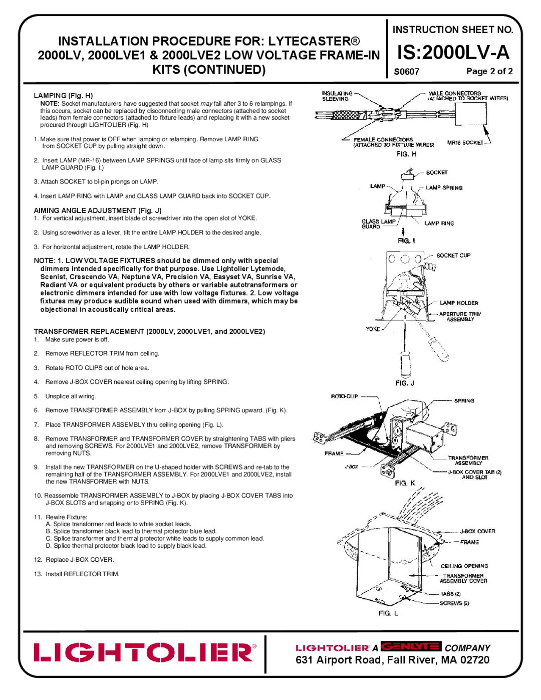
LAMPING (Fig. H)
NOTE: Socket manufacturers have suggested that socket may fail after 3 to 6 relampings. If this occurs, socket can be replaced by disconnecting male connectors (attached to socket leads) from female connectors (attached to fixture leads) and replacing it with a new socket procured through LIGHTOLIER (Fig. H)
1.Make sure that power is OFF when lamping or relamping. Remove LAMP RING from SOCKET CUP by pulling straight down.
2.Insert LAMP
3.Attach SOCKET to
4.Insert LAMP RING with LAMP and GLASS LAMP GUARD back into SOCKET CUP.
AIMING ANGLE ADJUSTMENT (Fig. J)
1.For vertical adjustment, insert blade of screwdriver into the open slot of YOKE.
2.Using screwdriver as a lever, tilt the entire LAMP HOLDER to the desired angle.
3.For horizontal adjustment, rotate the LAMP HOLDER.
NOTE: 1. LOW VOLTAGE FIXTURES should be dimmed only with special dimmers intended specifically for that purpose. Use Lightolier Lytemode, Scenist, Crescendo VA, Neptune VA, Precision VA, Easyset VA, Sunrise VA, Radiant VA or equivalent products by others or variable autotransformers or electronic dimmers intended for use with low voltage fixtures. 2. Low voltage fixtures may produce audible sound when used with dimmers, which may be objectional in acoustically critical areas.
TRANSFORMER REPLACEMENT (2000LV, 2000LVE1, and 2000LVE2)
1.Make sure power is off.
2.Remove REFLECTOR TRIM from ceiling.
3.Rotate ROTO CLIPS out of hole area.
4.Remove
5.Unsplice all wiring.
6.Remove TRANSFORMER ASSEMBLY from
7.Place TRANSFORMER ASSEMBLY thru ceiling opening (Fig. L).
8.Remove TRANSFORMER and TRANSFORMER COVER by straightening TABS with pliers and removing SCREWS. For 2000LVE1 and 2000LVE2, remove TRANSFORMER by removing NUTS.
9.Install the new TRANSFORMER on the
10.Reassemble TRANSFORMER ASSEMBLY to
11.Rewire Fixture:
A.Splice transformer red leads to white socket leads.
B.Splice transformer black lead to thermal protector blue lead.
C.Splice transformer and thermal protector white leads to supply common lead.
D.Splice thermal protector black lead to supply black lead.
12.Replace
13.Install REFLECTOR TRIM.
INSTRUCTION SHEET NO.
IS:2000LV-A
S0607 |
| Page 2 of 2 |
![]() A
A ![]() COMPANY
COMPANY
631 Airport Road, Fall River, MA 02720