INSTRUCTION SHEET NO.
IS:26600
A0397 | Page 2 of 4 |
Recessed ProSpec™ Track Mounting Methods
MOUNTING PROSPEC™ TRACK
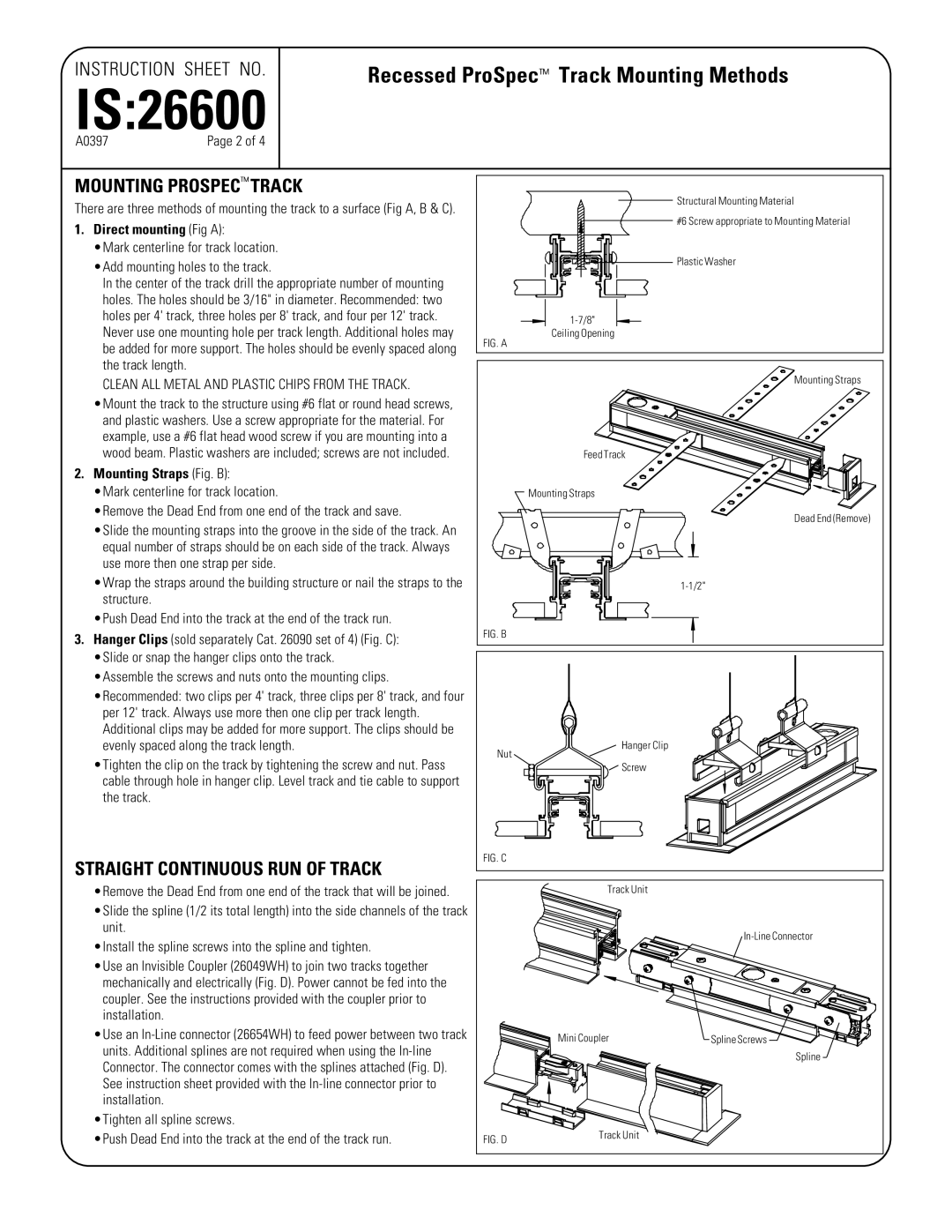
There are three methods of mounting the track to a surface (Fig A, B & C).
1.Direct mounting (Fig A):
•Mark centerline for track location. •Add mounting holes to the track.
In the center of the track drill the appropriate number of mounting holes. The holes should be 3/16" in diameter. Recommended: two holes per 4' track, three holes per 8' track, and four per 12' track.
Never use one mounting hole per track length. Additional holes may be added for more support. The holes should be evenly spaced along the track length.
CLEAN ALL METAL AND PLASTIC CHIPS FROM THE TRACK. •Mount the track to the structure using #6 flat or round head screws,
and plastic washers. Use a screw appropriate for the material. For example, use a #6 flat head wood screw if you are mounting into a wood beam. Plastic washers are included; screws are not included.
2.Mounting Straps (Fig. B):
•Mark centerline for track location.
•Remove the Dead End from one end of the track and save.
•Slide the mounting straps into the groove in the side of the track. An equal number of straps should be on each side of the track. Always use more then one strap per side.
•Wrap the straps around the building structure or nail the straps to the structure.
•Push Dead End into the track at the end of the track run.
3.Hanger Clips (sold separately Cat. 26090 set of 4) (Fig. C): •Slide or snap the hanger clips onto the track. •Assemble the screws and nuts onto the mounting clips. •Recommended: two clips per 4' track, three clips per 8' track, and four
per 12' track. Always use more then one clip per track length. Additional clips may be added for more support. The clips should be evenly spaced along the track length.
•Tighten the clip on the track by tightening the screw and nut. Pass cable through hole in hanger clip. Level track and tie cable to support the track.
STRAIGHT CONTINUOUS RUN OF TRACK
•Remove the Dead End from one end of the track that will be joined. •Slide the spline (1/2 its total length) into the side channels of the track
unit.
•Install the spline screws into the spline and tighten.
•Use an Invisible Coupler (26049WH) to join two tracks together mechanically and electrically (Fig. D). Power cannot be fed into the coupler. See the instructions provided with the coupler prior to installation.
•Use an
•Tighten all spline screws.
•Push Dead End into the track at the end of the track run.
Structural Mounting Material |
#6 Screw appropriate to Mounting Material |
Plastic Washer |
Ceiling Opening
FIG. A
Mounting Straps |
Feed Track |
Mounting Straps |
Dead End (Remove) |
FIG. B |
Hanger Clip |
Nut |
Screw |
FIG. C |
| Track Unit |
|
|
| |
| Mini Coupler | Spline Screws |
|
| Spline |
FIG. D | Track Unit |
|
|
|
