Instructions for Recessed ProSpec™ Track | INSTRUCTION SHEET NO. | ||
Power Feed to Track |
| IS:26600 | |
|
|
| |
|
| A0397 | Page 3 of 4 |
DIRECT POWER FEED TO "FEED" TRACK |
|
|
|
Use solid 12 ga. copper wire when feeding the track. The feed track accepts |
|
|
|
two separate 120 V, 60 Hz branch circuits. Each circuit must not exceed the | Electrical |
|
|
20 amp capacity of the track system. | Connector | Top Plate |
|
|
|
| |
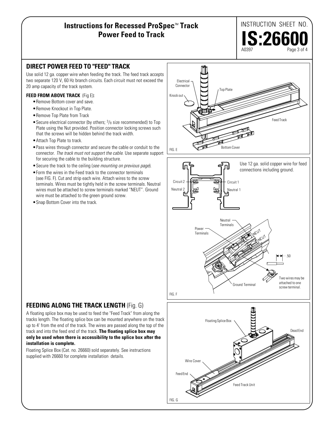
FEED FROM ABOVE TRACK (Fig E): | Knock out |
|
|
•Remove Bottom cover and save. |
|
|
|
•Remove Knockout in Top Plate. |
|
|
|
•Remove Top Plate from Track |
|
| Feed Track |
•Secure electrical connector (by others; 3/8 size recommended) to Top |
|
| |
|
|
| |
Plate using the Nut provided. Position connector locking screws such |
|
|
|
that the screws will be hidden behind the track width. |
|
|
|
•Attach Top Plate to track. |
|
|
|
•Pass wires through connector and secure the cable or conduit to the | FIG. E | Bottom Cover |
|
connector. The track must not support the cable. Use separate support |
|
| |
|
|
| |
for securing the cable to the building structure. |
| Use 12 ga. solid copper wire for feed | |
•Secure the track to the ceiling (see mounting on previous page). |
| ||
| connections including ground. | ||
•Form the wires in the Feed track to the connector terminals |
| ||
|
|
| |
(see FIG. F). Cut and strip each wire. Attach wires to the screw | Circuit 2 | Circuit 1 |
|
terminals. Wires must be tightly held in the screw terminals. Neutral |
| ||
|
|
| |
wires must be attached to screw terminals marked "NEUT”. Ground | Neutral 2 | Neutral 1 |
|
wire must be attached to the green ground screw. |
|
|
|
•Snap Bottom Cover into the track. |
|
|
|
|
| Neutral |
|
| Power | Terminals |
|
|
|
| |
| Terminals |
|
|
![]()
![]() .50
.50
| Two wires may be | |
Ground Terminal | attached to one | |
screw terminal. | ||
|
FIG. F
FEEDING ALONG THE TRACK LENGTH (Fig. G)
A floating splice box may be used to feed the "Feed Track" from along the tracks length. The floating splice box can be mounted anywhere on the track up to 4' from the end of the track. The wires are passed along the top of the track and into the feed end of the track. The floating splice box may only be used when there is accessibility to the splice box after the installation is complete.
Floating Splice Box (Cat. no. 26660) sold separately. See instructions supplied with 26660 for complete installation details.
Floating Splice Box |
Dead End |
Wire Cover |
Feed End |
Feed Track Unit |
FIG. G |
