Termination Clearances Sidewall Power Vent
POWER VENT
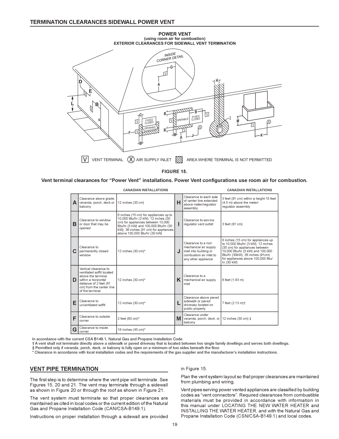
(using room air for combustion)
EXTERIOR CLEARANCES FOR SIDEWALL VENT TERMINATION
G
D
vE
L B
v
V
A
|
| C |
|
| B |
|
|
|
| B | V |
|
|
|
|
|
|
|
| FIXED | |||
|
|
|
|
|
|
|
| E | |||
| V |
| FIXED |
|
| V |
| OPERABL | CLOSED |
| |
|
|
|
|
|
|
| |||||
|
| CLOSED |
|
|
|
|
|
|
|
| |
|
|
|
|
|
|
|
|
|
|
| |
| V |
| OPERABL | E | B |
|
| V |
| X |
|
F |
|
|
|
|
|
|
| ||||
|
|
|
| B |
| J |
| ||||
|
|
|
|
|
|
|
| ||||
|
|
|
|
|
| A |
|
| |||
|
|
|
|
|
|
|
|
| |||
|
|
|
|
|
|
|
|
|
| ||
|
|
|
|
|
|
|
|
|
|
| |
|
| B |
|
|
|
|
|
|
|
|
|
H
M
V | X |
| |
| K |
V
VENT TERMINAL X AIR SUPPLY INLET | AREA WHERE TERMINAL IS NOT PERMITTED |
FIGURE 15.
Vent terminal clearances for “Power Vent” installations. Power Vent configurations use room air for combustion.
|
| Canadian Installations |
|
| Canadian Installations | |
|
|
|
|
|
| |
| Clearance above grade, |
|
| Clearance to each side | 3 feet (91 cm) within a height 15 feet | |
A |
| H | of center line extended | |||
veranda, porch, deck or | 12 inches (30 cm) | (4.5 m) above the meter/ | ||||
above meter/regulator | ||||||
| balcony |
|
| assembly | regulator assembly | |
|
|
|
|
| ||
|
|
|
|
|
| |
|
| 6 inches (15 cm) for appliances up to |
|
|
| |
| Clearance to window | 10,000 Btu/hr (3 kW), 12 inches (30 |
| Clearance to service |
| |
B | cm) for appliances between 10,000 | I |
| |||
or door that may be | regulator vent outlet | 3 feet (91 cm) | ||||
Btu/hr (3 kW) and 100,000 Btu/hr (30 | ||||||
| opened | kW), 36 inches (91 cm) for appliances |
|
|
| |
|
| above 100,000 Btu/hr (30 kW) |
|
|
| |
|
|
|
|
|
| |
|
|
|
| Clearance to a non | 6 inches (15 cm) for appliances up | |
|
|
|
| to 10,000 Btu/hr (3 kW), 12 inches | ||
C | Clearance to |
| J | mechanical air supply | (30 cm) for appliances between | |
permanently closed | 12 inches (30 cm)* | inlet into building or | 10,000 Btu/hr (3 kW) and 100,000 | |||
| window |
|
| combustion air inlet to | Btu/hr (30kW), 36 inches (91cm) | |
|
|
|
| any other appliance | for appliances above 100,000 Btu/ | |
|
|
|
|
| hr (30 kW) | |
| Vertical clearance to |
|
|
|
| |
| ventilated soffit located |
|
| Clearance to a |
| |
D | above the terminal | 12 inches (30 cm)* | K |
| ||
within a horizontal | mechanical air supply | 6 feet (1.83 m) | ||||
| distance of 2 feet (61 |
|
| inlet |
| |
| cm) from the center line |
|
|
|
| |
| of the terminal |
|
|
|
| |
| Clearance to |
|
| Clearance above paved |
| |
E | 12 inches (30 cm)* | L | sidewalk or paved | 7 feet (2.13 m)† | ||
unventilated soffit | driveway located on | |||||
|
|
|
| public property |
| |
F | cornerClearance to outside |
| M | Clearance under |
| |
2 feet (60 cm)* | veranda, porch, deck, or | 12 inches (30 cm) ‡ | ||||
|
|
|
| balcony |
| |
G | cornerClearance to inside | 18 inches (45 cm)* |
|
|
|
In accordance with the current CSA B149.1, Natural Gas and Propane Installation Code.
†A vent shall not terminate directly above a sidewalk or paved driveway that is located between two single family dwellings and serves both dwellings.
‡ Permitted only if veranda, porch, deck, or balcony is fully open on a minimum of two sides beneath the floor.
* Clearance in accordance with local installation codes and the requirements of the gas supplier and the manufacturer’s installation instructions.
VENT PIPE TERMINATION
The first step is to determine where the vent pipe will terminate. See Figures 15, 20 and 21. The vent may terminate through a sidewall as shown in Figure 20 or through the roof as shown in Figure 21.
The vent system must terminate so that proper clearances are maintained as cited in local codes or the current edition of the Natural Gas and Propane Installation Code
Instructions on proper installation through a sidewall are provided
in Figure 15.
Plan the vent system layout so that proper clearances are maintained from plumbing and wiring.
Vent pipes serving power vented appliances are classified by building codes as “vent connectors”. Required clearances from combustible materials must be provided in accordance with information in this manual under LOCATING THE NEW WATER HEATER and INSTALLING THE WATER HEATER, and with the Natural Gas and Propane Installation Code
19