SEDIMENT TRAPS
A sediment trap should be installed as close to the inlet of the water heater as practical at the time of water heater installation. The sediment trap should be either a tee fitting with a capped nipple in the bottom outlet or other device recognized as an effective sediment trap. If a tee fitting is used, it should be installed in conformance with one of the methods of installation shown in Figures 12 and 13.
Contaminants in the gas lines may cause improper operation of the gas control valve that may result in fire or explosion. Before attaching the gas line be sure that all gas pipe is clean on the inside. To trap any dirt or foreign material in the gas supply line, a drip leg (sometimes called a sediment trap) must be incorporated in the piping. The drip leg must be readily accessible. Install in accordance with the “Gas Piping” section. Refer to the current edition of the Natural Gas and Propane Installation Code (CAN/CSA B149.1).
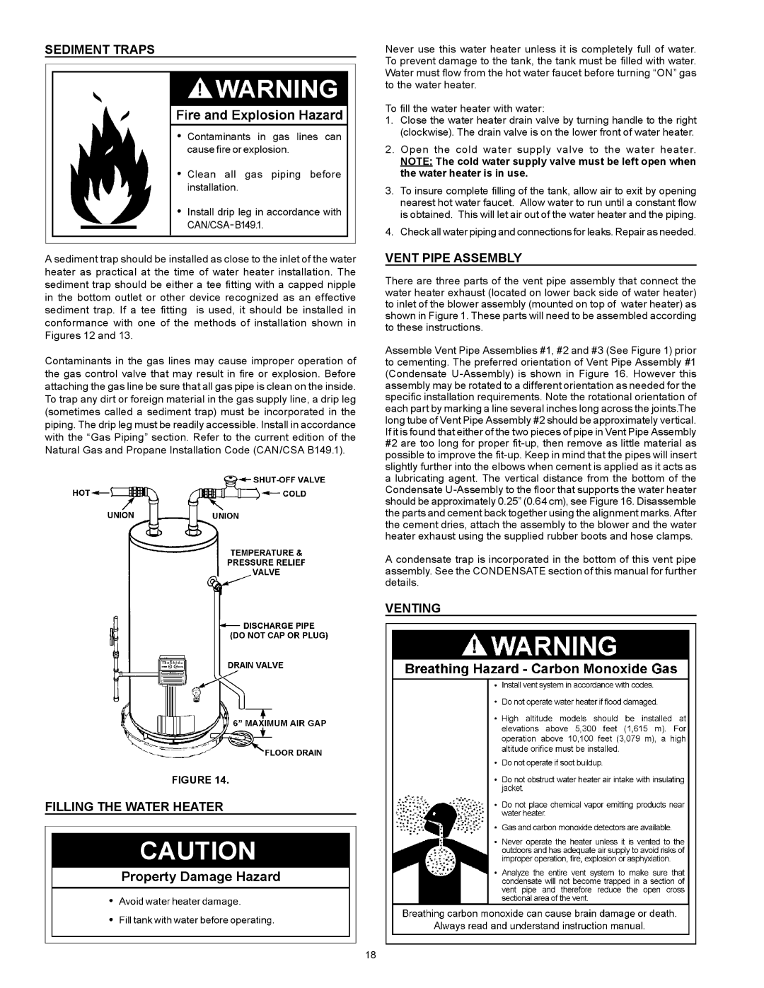
FIGURE 14.
Filling the Water Heater
Never use this water heater unless it is completely full of water. To prevent damage to the tank, the tank must be filled with water. Water must flow from the hot water faucet before turning “ON” gas to the water heater.
To fill the water heater with water:
1.Close the water heater drain valve by turning handle to the right (clockwise). The drain valve is on the lower front of water heater.
2.Open the cold water supply valve to the water heater.
NOTE: The cold water supply valve must be left open when the water heater is in use.
3.To insure complete filling of the tank, allow air to exit by opening nearest hot water faucet. Allow water to run until a constant flow is obtained. This will let air out of the water heater and the piping.
4.Check all water piping and connections for leaks. Repair as needed.
VENT PIPE ASSEMBLY
There are three parts of the vent pipe assembly that connect the water heater exhaust (located on lower back side of water heater) to inlet of the blower assembly (mounted on top of water heater) as shown in Figure 1. These parts will need to be assembled according to these instructions.
Assemble Vent Pipe Assemblies #1, #2 and #3 (See Figure 1) prior to cementing. The preferred orientation of Vent Pipe Assembly #1 (Condensate
A condensate trap is incorporated in the bottom of this vent pipe assembly. See the CONDENSATE section of this manual for further details.
VENTING
18