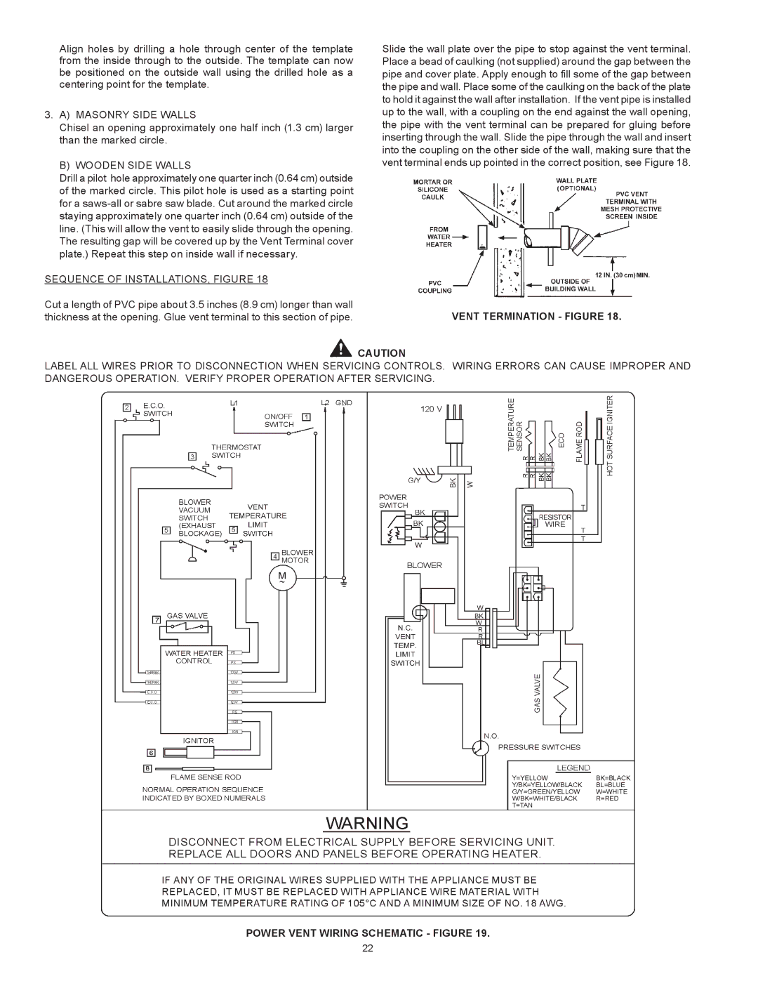
Align holes by drilling a hole through center of the template | Slide the wall plate over the pipe to stop against the vent terminal. |
from the inside through to the outside. The template can now | Place a bead of caulking (not supplied) around the gap between the |
be positioned on the outside wall using the drilled hole as a | pipe and cover plate. Apply enough to fill some of the gap between |
centering point for the template. | the pipe and wall. Place some of the caulking on the back of the plate |
| to hold it against the wall after installation. If the vent pipe is installed |
3. A) MASONRY SIDE WALLS | up to the wall, with a coupling on the end against the wall opening, |
Chisel an opening approximately one half inch (1.3 cm) larger | the pipe with the vent terminal can be prepared for gluing before |
than the marked circle. | inserting through the wall. Slide the pipe through the wall and insert |
| into the coupling on the other side of the wall, making sure that the |
B) WOODEN SIDE WALLS | vent terminal ends up pointed in the correct position, see Figure 18. |
Drill a pilot hole approximately one quarter inch (0.64 cm) outside |
|
of the marked circle. This pilot hole is used as a starting point |
|
for a |
|
staying approximately one quarter inch (0.64 cm) outside of the |
|
line. (This will allow the vent to easily slide through the opening. |
|
The resulting gap will be covered up by the Vent Terminal cover |
|
plate.) Repeat this step on inside wall if necessary. |
|
SEQUENCE OF INSTALLATIONS, FIGURE 18 |
|
Cut a length of PVC pipe about 3.5 inches (8.9 cm) longer than wall | VENT TERMINATION - FIGURE 18. |
thickness at the opening. Glue vent terminal to this section of pipe. |
![]() CAUTION
CAUTION
LABEL ALL WIRES PRIOR TO DISCONNECTION WHEN SERVICING CONTROLS. WIRING ERRORS CAN CAUSE IMPROPER AND DANGEROUS OPERATION. VERIFY PROPER OPERATION AFTER SERVICING.
POWER VENT WIRING SCHEMATIC - FIGURE 19.
22