exceed the marked hydrostatic working pressure of the water heater (150 psi = 1,035 kPa) and a discharge capacity not less than the water heater Btu/hr or kW input rate as shown on the water heater’s model rating plate.

Note: In addition to the factory installed
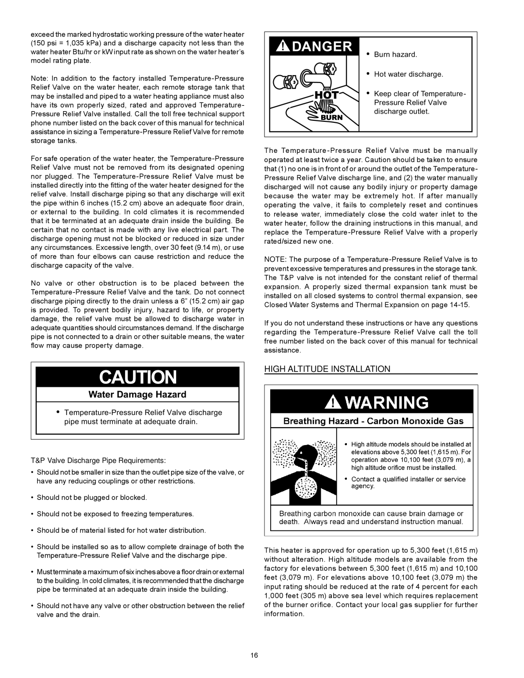
 Temperature-Pressure Relief Valve on the water heater, each remote storage tank that may be installed and piped to a water heating appliance must also have its own properly sized, rated and approved Temperature- Pressure Relief Valve installed. Call the toll free technical support phone number listed on the back cover of this manual for technical assistance in sizing a Temperature-Pressure Relief Valve for remote storage tanks.

DANGER

Burn hazard.

Hot water discharge.

Keep clear of Temperature- Pressure Relief Valve discharge outlet.

For safe operation of the water heater, the Temperature-Pressure Relief Valve must not be removed from its designated opening nor plugged. The Temperature-Pressure Relief Valve must be installed directly into the fitting of the water heater designed for the relief valve. Install discharge piping so that any discharge will exit the pipe within 6 inches (15.2 cm) above an adequate floor drain, or external to the building. In cold climates it is recommended that it be terminated at an adequate drain inside the building. Be certain that no contact is made with any live electrical part. The discharge opening must not be blocked or reduced in size under any circumstances. Excessive length, over 30 feet (9.14 m), or use of more than four elbows can cause restriction and reduce the discharge capacity of the valve.

No valve or other obstruction is to be placed between the Temperature-Pressure Relief Valve and the tank. Do not connect discharge piping directly to the drain unless a 6” (15.2 cm) air gap is provided. To prevent bodily injury, hazard to life, or property damage, the relief valve must be allowed to discharge water in adequate quantities should circumstances demand. If the discharge pipe is not connected to a drain or other suitable means, the water flow may cause property damage.

CAUTION

Water Damage Hazard

Temperature-Pressure Relief Valve discharge pipe must terminate at adequate drain.

T&P Valve Discharge Pipe Requirements:

Should not be smaller in size than the outlet pipe size of the valve, or have any reducing couplings or other restrictions.

Should not be plugged or blocked.

Should not be exposed to freezing temperatures.

Should be of material listed for hot water distribution.

Should be installed so as to allow complete drainage of both the

Temperature-Pressure Relief Valve and the discharge pipe.

Must terminate a maximum of six inches above a floor drain or external to the building. In cold climates, it is recommended that the discharge pipe be terminated at an adequate drain inside the building.

Should not have any valve or other obstruction between the relief valve and the drain.

The Temperature-Pressure Relief Valve must be manually operated at least twice a year. Caution should be taken to ensure that (1) no one is in front of or around the outlet of the Temperature- Pressure Relief Valve discharge line, and (2) the water manually discharged will not cause any bodily injury or property damage because the water may be extremely hot. If after manually operating the valve, it fails to completely reset and continues to release water, immediately close the cold water inlet to the water heater, follow the draining instructions in this manual, and replace the Temperature-Pressure Relief Valve with a properly rated/sized new one.

Note: The purpose of a Temperature-Pressure Relief Valve is to prevent excessive temperatures and pressures in the storage tank. The T&P valve is not intended for the constant relief of thermal expansion. A properly sized thermal expansion tank must be installed on all closed systems to control thermal expansion, see Closed Water Systems and Thermal Expansion on page 14-15.

If you do not understand these instructions or have any questions regarding the Temperature-Pressure Relief Valve call the toll free number listed on the back cover of this manual for technical assistance.

HIGH ALTITUDE INSTALLATION

This heater is approved for operation up to 5,300 feet (1,615 m) without alteration. High altitude models are available from the factory for elevations between 5,300 feet (1,615 m) and 10,100 feet (3,079 m). For elevations above 10,100 feet (3,079 m) the input rating should be reduced at the rate of 4 percent for each 1,000 feet (305 m) above sea level which requires replacement of the burner orifice. Contact your local gas supplier for further information.

16

Page 16
Image 16
Enviro 6G50 76N instruction manual High Altitude Installation, Valve Discharge Pipe Requirements