Figure 7. The water heater should have clearances of at least 1 inch (25 mm) from the sides and back and 6 inches (150 mm) from the front of the appliance. The opening should directly communicate with the outdoors or should communicate through a vertical or horizontal duct to the outdoors or spaces that freely communicate with the outdoors and should have a minimum free area of the following:
1.1 square inch per 3000 Btu/hr (700 mm2 per kW) of the total input rating of all appliances located in the enclosure, and
2.Not less than the sum of the areas of all vent connectors in space.
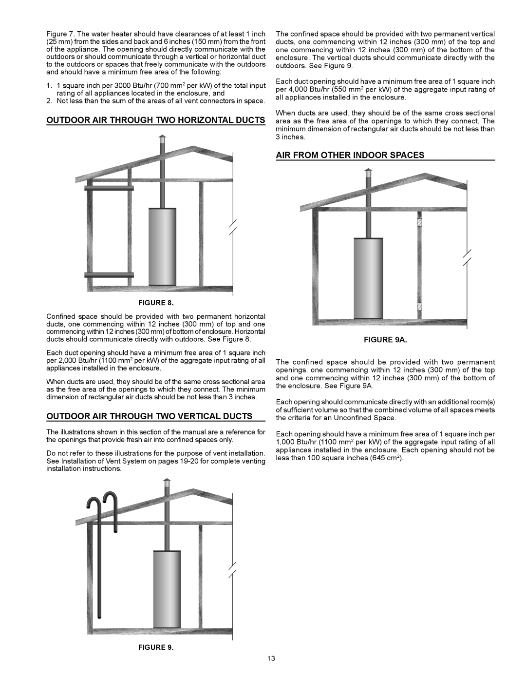
OUTDOOR AIR THROUGH TWO HORIZONTAL DUCTS
FIGURE 8.
Confined space should be provided with two permanent horizontal ducts, one commencing within 12 inches (300 mm) of top and one commencing within 12 inches (300 mm) of bottom of enclosure. Horizontal ducts should communicate directly with outdoors. See Figure 8.
Each duct opening should have a minimum free area of 1 square inch per 2,000 Btu/hr (1100 mm2 per kW) of the aggregate input rating of all appliances installed in the enclosure.
When ducts are used, they should be of the same cross sectional area as the free area of the openings to which they connect. The minimum dimension of rectangular air ducts should be not less than 3 inches.
OUTDOOR AIR THROUGH TWO VERTICAL DUCTS
The illustrations shown in this section of the manual are a reference for the openings that provide fresh air into confined spaces only.
Do not refer to these illustrations for the purpose of vent installation. See Installation of Vent System on pages
FIGURE 9.
The confined space should be provided with two permanent vertical
ducts, one commencing within 12 inches (300 mm) of the top and one commencing within 12 inches (300 mm) of the bottom of the enclosure. The vertical ducts should communicate directly with the outdoors. See Figure 9.
Each duct opening should have a minimum free area of 1 square inch per 4,000 Btu/hr (550 mm2 per kW) of the aggregate input rating of all appliances installed in the enclosure.
When ducts are used, they should be of the same cross sectional area as the free area of the openings to which they connect. The minimum dimension of rectangular air ducts should be not less than 3 inches.
AIR FROM OTHER INDOOR SPACES
FIGURE 9A.
The confined space should be provided with two permanent openings, one commencing within 12 inches (300 mm) of the top and one commencing within 12 inches (300 mm) of the bottom of the enclosure. See Figure 9A.
Each opening should communicate directly with an additional room(s)
of sufficient volume so that the combined volume of all spaces meets the criteria for an Unconfined Space.
Each opening should have a minimum free area of 1 square inch per 1,000 Btu/hr (1100 mm2 per kW) of the aggregate input rating of all appliances installed in the enclosure. Each opening should not be less than 100 square inches (645 cm2).
13