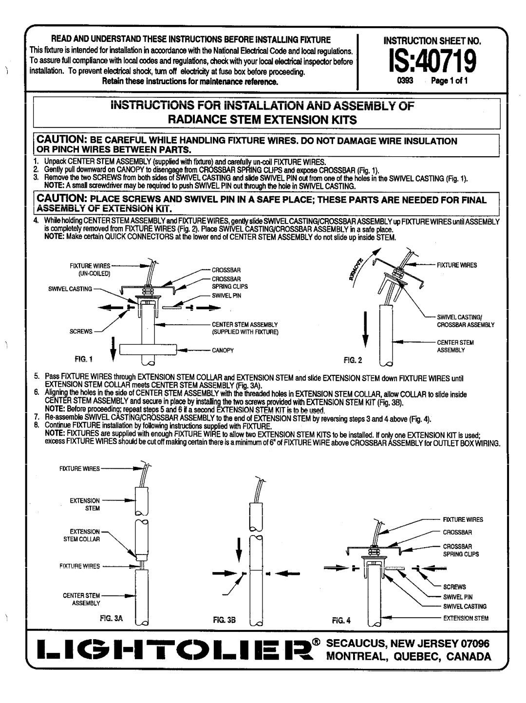
IS:40719 specifications
Lightolier IS:40719 is a highly versatile and sophisticated LED recessed downlight that has made its mark in the lighting industry, particularly known for its energy efficiency and modern design. This innovative lighting solution is engineered to provide superior illumination while seamlessly integrating into various architectural styles.One of the standout features of the Lightolier IS:40719 is its incredible energy efficiency. Utilizing advanced LED technology, this downlight consumes significantly less power than traditional incandescent or fluorescent fixtures. This not only helps in reducing electricity bills but also minimizes the carbon footprint, aligning with today’s growing demand for sustainable practices.
The IS:40719 is available in multiple wattage options, allowing for customized brightness levels suited to different spaces. This flexibility makes it ideal for residential, commercial, and retail applications, along with hospitality environments. With a color rendering index (CRI) that exceeds 90, the downlight ensures that colors appear vibrant and lifelike, enhancing the aesthetic appeal of any area it illuminates.
In addition to its functionality, the Lightolier IS:40719 features a sleek, low-profile design that lends itself to modern decor. Available in a variety of trim colors and finishes, it can easily blend in or stand out, depending on the desired look. Its slim construction allows for easy installation, and it is compatible with most existing ceiling structures, making retrofitting a painless process.
The advanced thermal management system incorporated in the IS:40719 ensures optimal performance and a long operational life. By efficiently dissipating heat, it prevents overheating and prolongs the lifespan of the LEDs, which can last upwards of 50,000 hours. This reliability translates to lower maintenance costs and fewer replacements over time.
The Lightolier IS:40719 also offers dimming capabilities, providing users with control over the ambiance of their spaces. This feature not only adds to its versatility but also contributes to further energy savings when lower light levels are sufficient.
With its impressive blend of efficiency, aesthetics, and innovative technology, the Lightolier IS:40719 is an excellent choice for those seeking a premium lighting solution that meets contemporary demands for performance and style.

