INSTRUCTION SHEET NO. |
| READ AND UNDERSTAND THESE INSTRUCTIONS BEFORE INSTALLING FIXTURE | |||
|
|
|
|
| |
IS:4A28442 |
|
| This luminaire is intended for installation in accordance with the National Electrical Code and local regulations. | ||
|
| To assure full compliance with local codes and regulations, check with your local electrical inspector before | |||
|
| installation. To prevent electric shock, turn off electricity at fuse box before proceeding. | |||
|
|
|
|
| Retain these instructions for maintenance reference. |
|
|
|
| ||
A0501 |
| Page 2 of 2 | |||
|
|
|
|
|
|
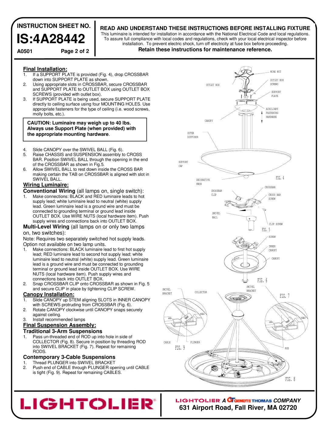
Final Installation:
1.If a SUPPORT PLATE is provided (Fig. 4), drop CROSSBAR down into SUPPORT PLATE as shown.
2.Using appropriate slots in CROSSBAR, secure CROSSBAR and SUPPORT PLATE to OUTLET BOX using OUTLET BOX SCREWS (provided with outlet box).
3.If SUPPORT PLATE is being used, secure SUPPORT PLATE directly to ceiling surface using four MOUNTING HOLES. Use appropriate fasteners for the type of ceiling (i.e. wood screws, molly bolts, etc.).
CAUTION: Luminaire may weigh up to 40 lbs. Always use Support Plate (when provided) with the appropriate mounting hardware.
4.Slide CANOPY over the SWIVEL BALL (Fig. 6).
5.Raise CHASSIS and SUSPENSION assembly to CROSS BAR. Position SWIVEL BALL through the opening in the end of the CROSSBAR as shown in Fig.5.
6.Allow SWIVEL BALL to rest down inside the CROSS BAR making certain the TAB on CROSSBAR is aligned with slot in
SWIVEL BALL.
Wiring Luminaire:
Conventional Wiring (all lamps on, single switch):
1.Make connections: BLACK and RED luminaire leads to hot supply lead; white luminaire lead to neutral (white) supply lead. Green luminaire lead is a ground wire and must be connected to grounding terminal or ground lead inside OUTLET BOX. Use WIRE NUTS (local hardware item). Push supply wires and connections back into OUTLET BOX.
Note: Requires two separately switched hot supply leads. Option not available on two lamp units.
1.Make connections: BLACK luminaire lead to first hot supply lead; RED luminaire lead to second hot supply lead; white luminaire lead to neutral (white) supply lead. Green luminaire lead is a ground wire and must be connected to grounding terminal or ground lead inside OUTLET BOX. Use WIRE NUTS (local hardware item). Push supply wires and connections back into OUTLET BOX.
2.Snap CROSSBAR CLIP onto CROSSBAR as shown in Fig. 5 and secure CLIP in place by tightening CLIP SCREW.
Canopy Installation:
1.Slide CANOPY up STEM aligning SLOTS in INNER CANOPY with SCREWS protruding from CROSSBAR (Fig. 6).
2.Rotate CANOPY clockwise until CANOPY snaps securely against ceiling.
3.Install recommended lamps
Final Suspension Assembly:
Traditional 3-Arm Suspensions
1.Pass
Contemporary 3-Cable Suspensions
1.Thread PLUNGER into SWIVEL BRACKET
2.Push end of CABLE through PLUNGER opening until CABLE is tight (Fig. 9). Repeat for remaining CABLES.
|
| WIRE NUT | |
|
| OUTLET BOX | |
| OUTLET BOX | SCREWS | |
|
| SUPPORT | |
|
| PLATE | |
|
| AUXILIARY | |
|
| FASTENING | |
|
| HARDWARE | |
| CANOPY |
| |
| OUTER |
| |
| DIFFUSER |
| |
| SUPPORT |
| |
| CAP |
| |
| DECORATIVE | FIG. 4 | |
|
| ||
| KNOB | CROSSBAR | |
|
| ||
| CROSSBAR |
| |
| CLIP | CROSS BAR | |
|
| SCREW | |
| SWIVEL |
| |
| BALL |
| |
|
| CLIP SCREW | |
|
| FIG. 5 | |
|
| SCREW | |
|
| INNER | |
|
| CANOPY | |
|
| CANOPY | |
|
| FIG. 6 | |
SWIVEL |
| SWIVEL | |
COLLECTOR | BRACKET | ||
BRACKET | |||
FIG. 7 | |||
| |||
|
| ||
CABLE | PLUNGER |
| |
| FIG. 9 | ROD | |
|
| FIG. 8 | |
| A | COMPANY |
631 Airport Road, Fall River, MA 02720