READ AND UNDERSTAND THESE INSTRUCTIONS BEFORE INSTALLING LUMINAIRE
This luminaire is intended for installation in accordance with the National Electrical Code and local regulations. To
assure full compliance with local codes and regulations, check with your local electrical inspector before
installation. To prevent electric shock, turn off electricity at fuse box before proceeding.
Retain these instructions for maintenance reference.
INSTRUCTION SHEET NO.
IS:4A28442
A0501 |
| Page 1 of 2 |
INSTRUCTIONS FOR INSTALLATION OF PENDALUX PENDANT SERIES
Note: This instruction sheet covers several luminaire (fixture) styles. Although suspension, chassis, lamp type and diffuser may vary from that shown, installation is the same.
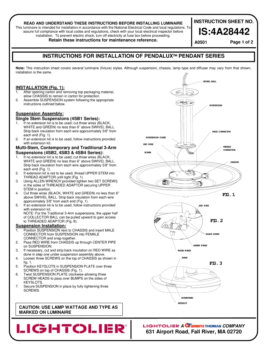
SWIVEL BALL
INSTALLATION (Fig. 1):
1.After opening carton and removing top packaging material, allow CHASSIS to remain in carton for protection.
2.Assemble SUSPENSION system following the appropriate
instructions outlined below. | SUSPENSION |
Suspension Assembly:
Single Stem Suspensions (4SB1 Series):
1.If no extension kit is to be used; cut three wires (BLACK, WHITE and GREEN) no less than 6” above SWIVEL BALL.
Strip back insulation from each wire approximately 3/8” from | MALE CONNECTOR | |
each end (Fig. 1). | SUSPENSION PLATE | |
2. If an extension kit is to be used, follow instructions provided | ||
| ||
with extension kit. | RED WIRE | |
| CONNECTOR | |
Suspensions (4SB2, 4SB3 & 4SB4 Series): | FEMALE | |
SCREW | ||
|
1.If no extension kit is to be used; cut three wires (BLACK,
| WHITE and GREEN) no less than 6” above SWIVEL BALL. | CHASSIS |
| Strip back insulation from each wire approximately 3/8” from |
|
| each end (Fig. 1). |
|
2. | If extension kit is not to be used, thread UPPER STEM into |
|
| THREAD ADAPTOR until tight (Fig. 1). |
|
3. | Using ALLEN WRENCH provided tighten two SET SCREWS |
|
| in the sides of THREADED ADAPTOR securing UPPER |
|
| STEM in position. |
|
4. | Cut three wires (BLACK, WHITE and GREEN) no less than 6” | FIG.1 |
| above SWIVEL BALL. Strip back insulation from each wire | |
|
| |
| approximately 3/8” from each end (Fig. 1). |
|
5. | If an extension kit is to be used, follow instructions provided | RED WIRE |
| with extension kit. |
|
| NOTE: For the Traditional |
|
| of COLLECTOR BALL can be pulled upward to gain access | FIG.2 |
| to THREADED ADAPTOR (Fig. 8). |
Suspension Installation:
1.Position SUSPENSION next to CHASSIS and insert MALE
CONNECTOR from SUSPENSION into FEMALE | BLACK WIRES |
CONNECTOR and snap together. |
|
2.Pass RED WIRE from CHASSIS up through CENTER PIPE
| on SUSPENSION. | GREEN WIRES |
|
| |
3. | If necessary, cut and strip back insulation on RED WIRE as | WHITE WIRES |
| done in step one under suspension assembly above. |
|
4. | Loosen three SCREWS on the top of CHASSIS as shown in | BUMP |
5. | fig. 1. | FIG.3 |
Position KEYSLOTS in SUSPENSION PLATE over three |
| |
| SCREWS on top of CHASSIS (Fig. 1). |
|
6. | Twist SUSPENSION PLATE clockwise allowing three |
|
| SCREW HEADS to pass over BUMPS on the sides of |
|
| KEYSLOTS. |
|
7. | Secure SUSPENSION in place by fully tightening three |
|
| SCREWS. |
|
|
| SCREWHEAD |
|
| KEYSLOT |
CAUTION: USE LAMP WATTAGE AND TYPE AS
MARKED ON LUMINAIRE
![]() A
A ![]() COMPANY
COMPANY
631 Airport Road, Fall River, MA 02720