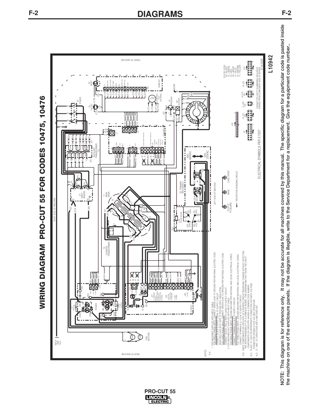
WIRING DIAGRAM PRO-CUT 55 FOR CODES 10475, 10476

INPUT

RIGHT SIDE OF MACHINE

PER


N.A.


G


F-2


C1

1200/450

-

+

203A

206

208

205

RELAY


++VOLT


P_XFMR

209


4

1

501

505

5

2

502


506

207 F -

207A

D1

INPUT

BRIDGE

209 D+

H1 H1

C

TP1 TP3

B

TP2

A

A

1

H1

N

8

53


H2

5

12V

3

56


N

2

H3

R

2

51


7

H4

24V

6

54


R

8

H5

U

9

64


4

H6

18V

5

62

W

J22


18V U

4

61


J21


AUXILIARY


W

R

B


W

V

U


S1


POWER


S3

S2


PSI_SET

RESET

277B


POWER

204

201

6

3

503

507

J10


TRANSFORMER

T2

277A

221

223

PRO-CUT 55

REAR OF MACHINE

H3 H1

FAN

FAN

FAN

MOTORS


xxxxxxx

404


202A

207A


+ C2-


1200/450


X4

J33


R


ELEC

3

1

W


XFER


ELEC

XFER

4

2

R


W


X2


X40


X20


B21


J31


6

1

366

4


7

2

2


1,2 TRIGGER

8

3

369

360


3 NOZZLE


4 ELECTRODE

9

4

364

E


5,6 AIR SOL

365


7,8 ELEC SOL

10

5

361


10 WORK


J32


8

1

309


9

2

310


8 AIR SOL


2 ELEC SOL

10

3


344


3 TRIGGER

11

4


13 IGBT


T3

CURRENT TRANSFORMER

Y

Y


I


3

204

UT S


208

-O


BK

S


-IN


K


B


A

X4

N.C.


2

01


T1


205


MAIN

I


XFMR


T


U


B


-O

-IN


FR


S

FR


6

S


2


X2


S

-IN

S


FR


7


OUT

X20


-


FR


X1

X3

X30


W


X10


S

365

N N


-IN


T


K


B

-OU

360


S

K


B


X40


61

62 64


216

15

+15V


18V

18V


217

14

READY LED


J5


1

2


212

13

LOW_PSI LED


3

4


218

12

POT WIPER


507

4

8


213

11


503

3

7

P_XFMR

J1


RESET

502

506

2

6

++VOLT


219

10

GND

501

505

1

5

RELAY


6

1


214

9

THERMAL LED


216

212


210

8

RESET LED


Y


J4


7

2

217


215

7

PSI SET


3


8

3

213


Y

6

CT


218


6


2

5


9

4

214


275


401404


219


5


1

4

TSTAT


10

5

215


276


J2


210


4


J3


223

3


W

8

16

7,8 ELEC SHUNT (TWIST PR)


277

2


R

7

15


221

1


306

6

14


275

R1

J40


W

5

13 4,5 XFER SHUNT (TWIST PR)


276


R

4

12

12 GND


10K


312

11 TRIGGER


277

2W


303

3

11

3 IGBT


CONTROL


344

302

2

10

2,6 PSI SWITCH


277A

POT

DISPLAY

310


1

9

10 ELEC SOL


CW (MAX)


9 AIR SOL


309


CONTROL


J20


302


4

W


2

Y


S5


1


PRESSURE


306

R


WORK

FRONT OF MACHINE

DIAGRAMS

14 GND

12

5

303


13

6


A

0.6A

A

361

AIR

W

366

SOLENOID


NOTES:


14

7

312


J30


4

1

54

51


1,4=24V

5

2


G


5356

OUTPUT

12V 6

3


L1CHOKE


xxxxxxx

S

E


401


200-

208V

380-

415V

SLOW BLOW

H2 H3 H3

220-

230V

440-

460V

H4 H5

S4

PRIMARY


RECONNECT


202A

207

206

202


203 203

202

203A


N

N

4

2

400-

7

8


369

460VAC

6

9


364


5


E


4


1


200-

3

2


230VAC


N.A.

1. FOR MACHINES SUPPLIED WITH INPUT CABLE

FOR SINGLE PHASE INPUT: CONNECT GREEN LEAD TO GROUND PER NATIONAL ELECTRIC CODE.

CONNECT BLACK & WHITE LEADS TO SUPPLY CIRCUIT. WRAP RED LEAD WITH TAPE TO PROVIDE 600V. INSULATION.

FOR THREE PHASE INPUT: CONNECT GREEN LEAD TO GROUND PER NATIONAL ELECTRIC CODE. CONNECT BLACK, RED & WHITE LEADS TO SUPPLY CIRCUIT.

2. FOR MACHINES NOT SUPPLIED WITH INPUT CABLE

FOR SINGLE PHASE INPUT: GROUND MACHINE PER NATIONAL AND LOCAL ELECTRICAL CODES. CONNECT TERMINALS U & W TO SUPPLY CIRCUIT.

FOR THREE PHASE INPUT: GROUND MACHINE PER NATIONAL AND LOCAL ELECTRICAL CODES. CONNECT TERMINALS U, V & W TO SUPPLY CIRCUIT.

N.B. SINCE COMPONENTS OR CIRCUITRY OF A PRINTED CIRCUIT BOARD MAY CHANGE WITHOUT AFFECTING THE INTERCHANGEABILITY OF A COMPLETE BOARD, THIS DIAGRAM MAY NOT SHOW THE EXACT

COMPONENTS OR CIRCUITRY HAVING A COMMON CODE NUMBER. N.C. PLACE "A" LEAD ON APPROPRIATE CONNECTION FOR INPUT VOLTAGE.

CONNECTION SHOWN IS FOR 440-460V OPERATION.

N.D. C1 AND C2 CAPACITORS ARE A MATCHED SET.

LEFT SIDE OF MACHINE


COLOR CODE:


OUTPUT

BASE

CASE FRONT


B = BLACK


G = GREEN


PC BOARD


J40


R = RED


W = WHITE


1


15


U = BLUE


PROTECTIVE BONDING CIRCUIT


N = BROWN


Y = YELLOW


J3


J2,J21,

J1,J20,

J4,J10,

J5,J22


J30


J32


J31

J33


7


1

8

1

5

1

2

1

3

1

4

1


9

16

6

10

3

4

4

6

5

8

8

14


ELECTRICAL SYMBOLS PER E1537


CONNECTOR CAVITY NUMBERING SEQUENCE


(VIEWED FROM COMPONENT SIDE OF BOARD)


8-18-2000F

L10942

NOTE: This diagram is for reference only. It may not be accurate for all machines covered by this manual. The specific diagram for a particular code is pasted inside the machine on one of the enclosure panels. If the diagram is illegible, write to the Service Department for a replacement. Give the equipment code number..

F-2

Page 30
Image 30
Lincoln Electric 10475, 10473, 10476, 10474 manual Diagrams

10476, 10474, 10473, 10475 specifications

Lincoln Electric is renowned for its commitment to quality in arc welding equipment, and its models 10475, 10473, 10474, and 10476 are no exceptions. These products showcase advanced technologies designed to enhance user experience and improve weld quality across various applications.

The Lincoln Electric 10475 is a premier choice for professionals seeking exceptional portability and efficiency in stick welding. This model features a lightweight design that makes it easily transportable, ideal for fieldwork. It boasts a robust output range, allowing it to handle various electrode sizes, making it versatile for different metal types. The 10475 also incorporates a built-in electronic device that reduces the chance of arc blow, ensuring a stable arc when welding in challenging environments.

The 10473 model stands out for its innovative inverter technology, which significantly enhances energy efficiency. This unit reduces power consumption without sacrificing performance, making it an environmentally conscious choice for industrial applications. It features an intuitive interface, allowing users to adjust settings easily and quickly. The 10473 is designed to support TIG and stick welding with smooth arc control, promoting consistent welds and minimal spatter.

Model 10474 continues the trend of advanced technology with its synergic control feature, which automatically adjusts welding parameters based on the material and thickness. This functionality takes the guesswork out of settings, making it user-friendly for both beginners and seasoned welders. Additionally, the 10474 is equipped with a fan-on-demand system, reducing noise and improving energy efficiency while ensuring optimal cooling during extensive use.

Lastly, the 10476 model excels in dual function capabilities, providing users with the option for both MIG and flux-cored welding. This flexibility expands the range of applications, from thin sheet metal to thick structures. The 10476 also integrates a high duty cycle, making it suitable for continuous operation on demanding projects. Features such as advanced digital displays support precise control over voltage and wire feed speed, ensuring high-quality results.

Together, these Lincoln Electric models reflect the company's dedication to innovation and excellence in welding technologies. Their unique features cater to a wide array of welding needs, making them essential tools for professionals across various industries. Whether for portability, efficiency, user-friendliness, or versatility, Lincoln Electric continues to set the standard in welding equipment.