OPERATION | ||
|
|
|
4.ARC CONTROL- The ARC CONTROL dial is active in the
DOWNHILL PIPE mode: In this mode, the ARC CONTROL dial sets the short circuit current
5.WELD OUTPUT TERMINALS WITH FLANGE NUT- Provides a connection point for the electrode and
work cables.
6.GROUND STUD- Provides a connection point for connecting the machine case to earth ground.
7.
8.
9.WELD TERMINALS CONTROL SWITCH- In the WELD TERMINALS ON position, the output is electrically hot all the time. In the REMOTELY CONTROLLED posi- tion, the output is controlled by a wire feeder or amptrol device, and is electrically off until a remote switch is depressed.
10. WIRE FEEDER VOLTMETER SWITCH:
Matches the polarity of the wire feeder voltmeter to the polarity of the electrode.
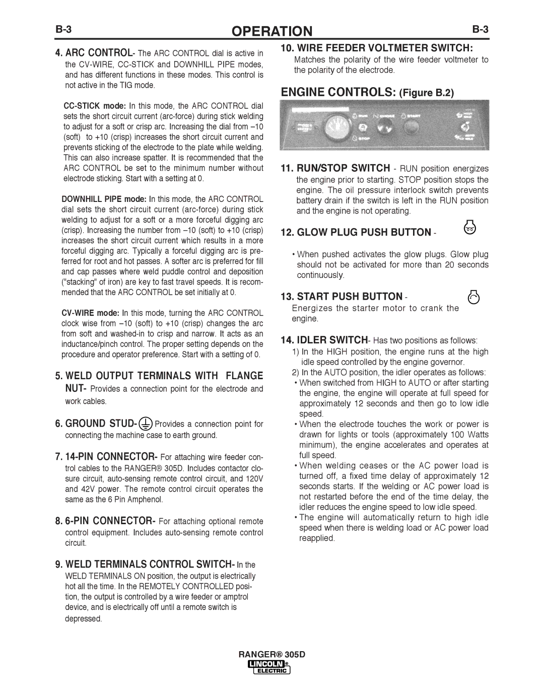
ENGINE CONTROLS: (Figure b.2)
11.RUN/STOP SWITCH - RUN position energizes the engine prior to starting. STOP position stops the engine. The oil pressure interlock switch prevents battery drain if the switch is left in the RUN position and the engine is not operating.
12. GLOW PLUG PUSH bUTTON -
•When pushed activates the glow plugs. Glow plug should not be activated for more than 20 seconds continuously.
13.START PUSH bUTTON -
Energizes the starter motor to crank the engine.
14.IDLER SWITCH- Has two positions as follows:
1)In the HIGH position, the engine runs at the high idle speed controlled by the engine governor.
2)In the AUTO position, the idler operates as follows:
• When switched from HIGH to AUTO or after starting the engine, the engine will operate at full speed for approximately 12 seconds and then go to low idle speed.
• When the electrode touches the work or power is drawn for lights or tools (approximately 100 Watts minimum), the engine accelerates and operates at full speed.
• When welding ceases or the AC power load is turned off, a fixed time delay of approximately 12 seconds starts. If the welding or AC power load is not restarted before the end of the time delay, the idler reduces the engine speed to low idle speed.
• The engine will automatically return to high idle speed when there is welding load or AC power load reapplied.
RANGER® 305D
