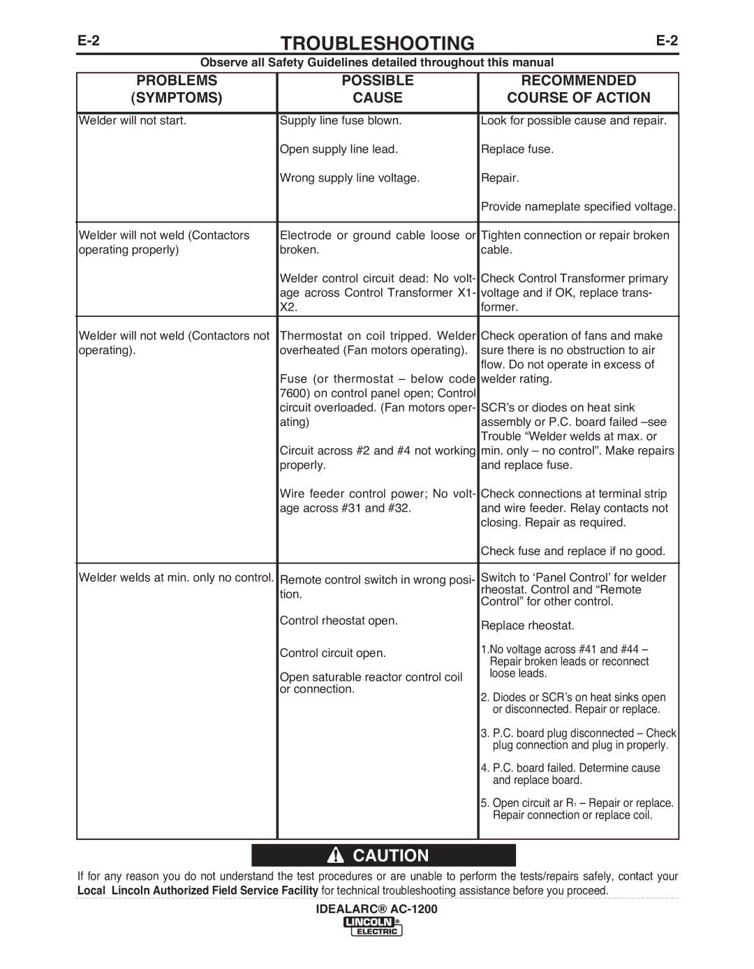
TROUbLESHOOTING | ||
|
|
|
| Observe all Safety Guidelines detailed throughout this manual |
|
|
|
|
PRObLEMS
(SYMPTOMS)
POSSIbLE
CAUSE
RECOMMENDED
COURSE OF ACTION
Welder will not start. | Supply line fuse blown. | Look for possible cause and repair. |
| Open supply line lead. | Replace fuse. |
| Wrong supply line voltage. | Repair. |
|
| Provide nameplate specified voltage. |
|
|
|
Welder will not weld (Contactors | Electrode or ground cable loose or | Tighten connection or repair broken |
operating properly) | broken. | cable. |
| Welder control circuit dead: No volt- | Check Control Transformer primary |
| age across Control Transformer X1- | voltage and if OK, replace trans- |
| X2. | former. |
|
|
|
Welder will not weld (Contactors not | Thermostat on coil tripped. Welder | Check operation of fans and make |
operating). | overheated (Fan motors operating). | sure there is no obstruction to air |
|
| flow. Do not operate in excess of |
| Fuse (or thermostat – below code | welder rating. |
| 7600) on control panel open; Control |
|
| circuit overloaded. (Fan motors oper- | SCR’s or diodes on heat sink |
| ating) | assembly or P.C. board failed |
|
| Trouble “Welder welds at max. or |
| Circuit across #2 and #4 not working | min. only – no control”. Make repairs |
| properly. | and replace fuse. |
| Wire feeder control power; No volt- | Check connections at terminal strip |
| age across #31 and #32. | and wire feeder. Relay contacts not |
|
| closing. Repair as required. |
|
| Check fuse and replace if no good. |
|
|
|
Welder welds at min. only no control. | Remote control switch in wrong posi- | Switch to ‘Panel Control’ for welder |
| tion. | rheostat. Control and “Remote |
| Control” for other control. | |
|
| |
| Control rheostat open. | Replace rheostat. |
|
| |
| Control circuit open. | 1.No voltage across #41 and #44 – |
| Repair broken leads or reconnect | |
|
| |
| Open saturable reactor control coil | loose leads. |
|
| |
| or connection. | 2. Diodes or SCR’s on heat sinks open |
|
| |
|
| or disconnected. Repair or replace. |
|
| 3. P.C. board plug disconnected – Check |
|
| plug connection and plug in properly. |
|
| 4. P.C. board failed. Determine cause |
|
| and replace board. |
|
| 5. Open circuit ar R1 – Repair or replace. |
|
| Repair connection or replace coil. |
|
|
|
![]() CAUTION
CAUTION
If for any reason you do not understand the test procedures or are unable to perform the tests/repairs safely, contact your Local Lincoln Authorized Field Service Facility for technical troubleshooting assistance before you proceed.
IDEALARC®
