DIAGRAMS | ||
|
|
|
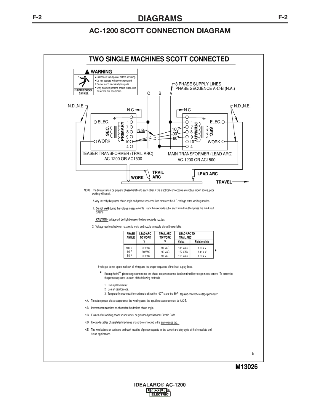
AC-1200 SCOTT CONNECTION DIAGRAM
TWO SINGLE MACHINES SCOTT CONNECTED
WARNING |
|
|
|
Disconnect input power before servicing. |
|
|
|
Do not operate with covers removed. |
|
| 3 PHASE SUPPLY LINES |
Do not touch electrically live parts. |
|
| |
Only qualified persons should install, use |
|
| PHASE SEQUENCE |
ELECTRIC SHOCK or service this equipment. | C | B | A |
CAN KILL | |||
N.D.,N.E. |
|
| N.D.,N.E. |
N.C. |
|
| N.C. |
ELEC. | PRIMARY | 1 |
|
|
|
| 1 | PRIMARY | ELEC. |
SEC. | 7 | N.B. |
| 100 | 7 | SEC. | |||
8 |
| 8 | |||||||
|
| 90 |
| ||||||
9 |
|
|
| 9 | |||||
|
| 80 |
| ||||||
WORK |
| 10 |
|
|
|
| 10 |
| WORK |
|
| 4 |
|
|
|
| 4 |
|
|
TEASER TRANSFORMER (TRAIL ARC) | MAIN TRANSFORMER (LEAD ARC) | ||||||||
|
| ||||||||
|
|
|
| TRAIL |
|
|
|
| LEAD ARC |
|
|
| WORK | ARC |
|
|
|
| |
|
|
|
|
|
|
| TRAVEL | ||
|
|
|
|
|
|
|
|
| |
NOTE: The two arcs must be properly phased relative to each other, if the electrical connections are not as shown above, poor welding will result.
A way to verify the proper phase angle and phase sequence is to measure the A.C. voltage at the welding nozzles.
1.Do not weld during the voltage measurements. Back the electrode out of each wire drive,then press the
CAUTION - Voltage will be high between the two electrode nozzles.
2.Voltage readings between nozzles to work, and nozzle to nozzle should be per table:
PHASE | LEAD ARC | TRAIL ARC | LEAD ARC TO |
|
| |
ANGLE | TO WORK | TO WORK | TRAIL ARC |
|
| |
| V | V | Value |
| Relationship |
|
|
|
|
|
|
|
|
100 o | 90 VAC | 90 VAC | 138 VAC |
| 1.53 x V | * |
90 o | 90 VAC | 90 VAC | 127 VAC |
| 1.41 x V | |
80 o | 90 VAC | 90 VAC | 116 VAC |
| 1.29 x V |
|
If voltages do not agree, recheck all wiring and the proper sequence of the input supply lines.
* If using the 90 o phase angle connection, the phase sequence cannot be determined by voltage measurement. To determine the phase sequence use one of the following methods.
1.Use a phase meter.
2.Use an oscilloscope.
3. Temporarily reconnect the machine to either the 100o tap or the 80 o tap and check the voltage per note 2.
N.A. To obtain proper phase sequence at the welding arcs, the input line sequence must be
N.B. Interconnect machines as shown for the desired phase angle.
N.C. Frames of all welding power sources must be grounded per National Electric Code.
N.D. Electrode cables of paralleled machines should be connected to the same range tap.
N.E. The weld cables for each arc, and work must be of proper capacity for the current and duty cycle of the immediate and future applications.
B
M13026
IDEALARC®